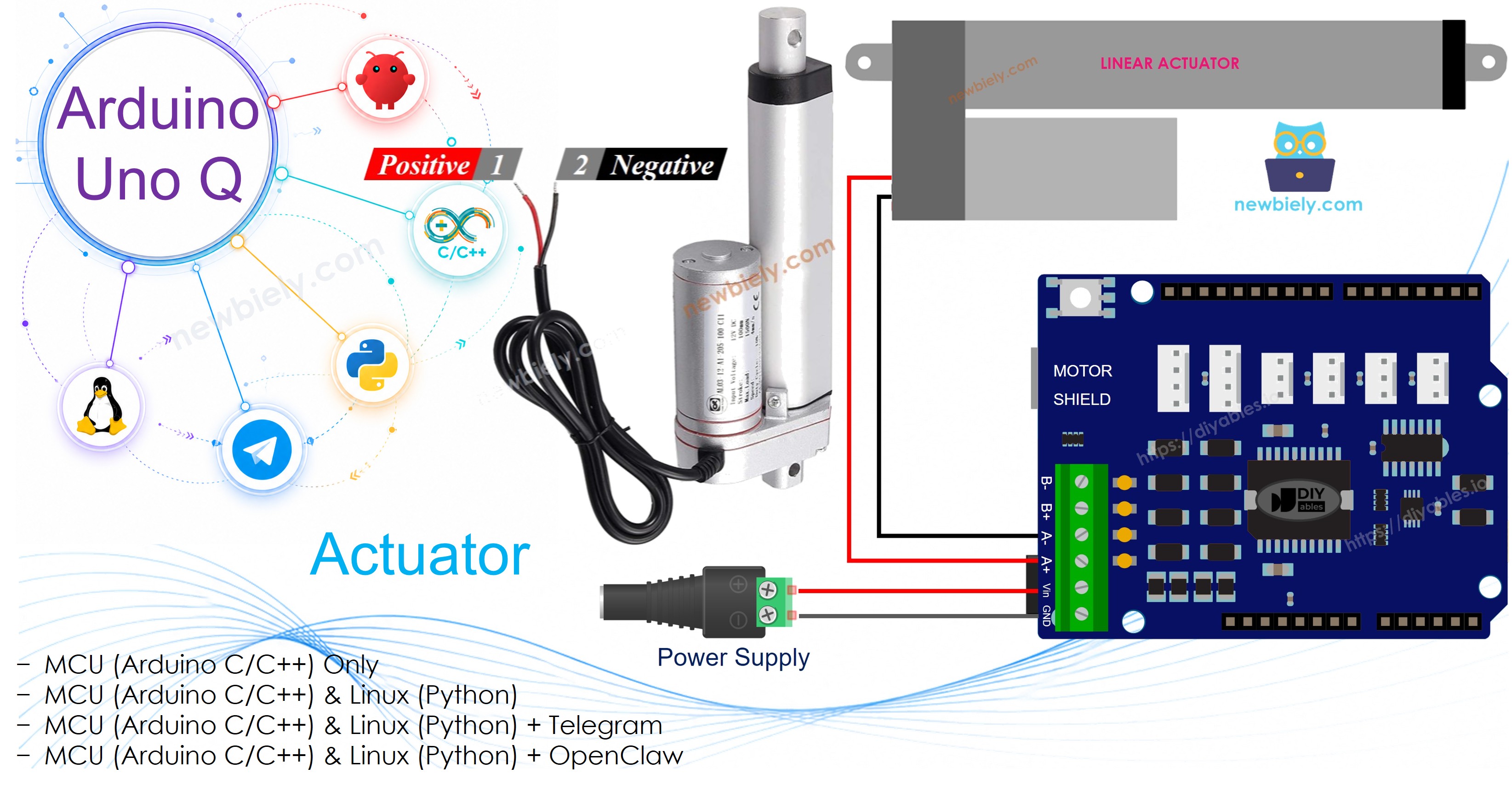
Arduino UNO Q - Actuator
In this guide, you will learn how to control a linear actuator with Arduino UNO Q and the Motor Shield Rev3. You will learn:
- How a linear actuator works
- How to wire the actuator with the Motor Shield Rev3
- How to extend and retract the actuator from MCU code
- How to control the actuator from Linux via the Bridge
- How to control the actuator remotely over Telegram
This tutorial covers linear actuators without feedback. For position control, see Arduino UNO Q - Actuator with Feedback.
Hardware Preparation
Or you can buy the following kits:
| 1 | × | DIYables Sensor Kit (18 sensors/displays) |
Additionally, some of these links are for products from our own brand, DIYables .
Overview of Linear Actuator

A linear actuator converts electrical energy into linear motion. It can extend and retract, making it useful for pushing, pulling, lifting, or clamping.
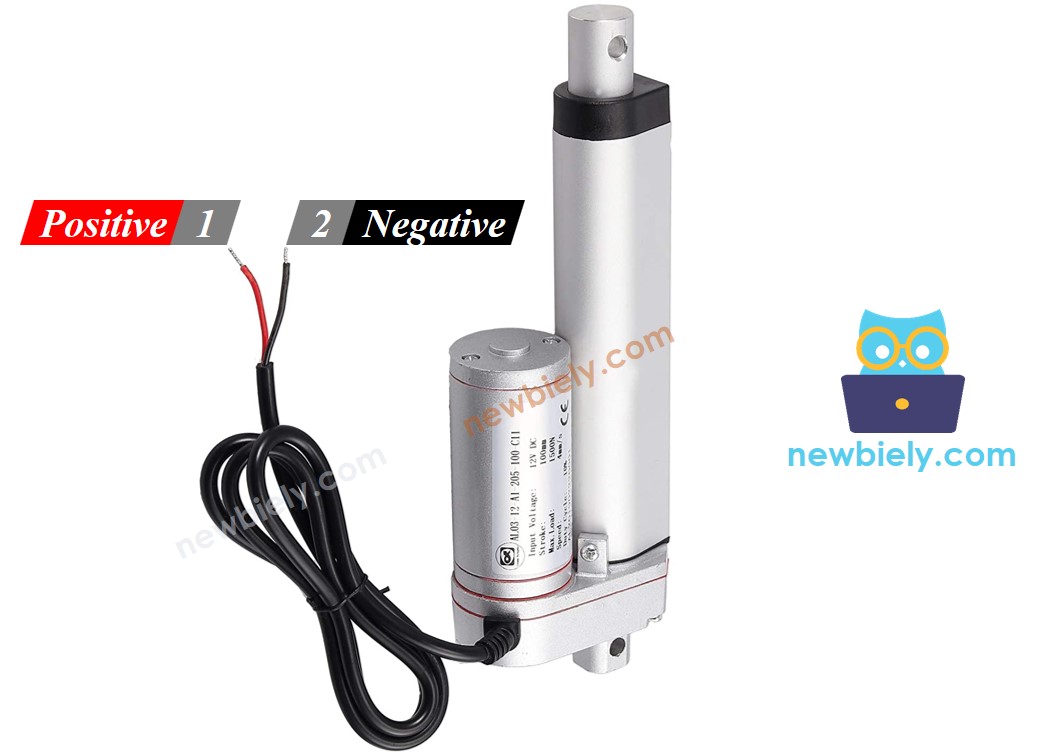
Linear Actuator Pinout
A linear actuator has two wires:
- Positive wire (often red)
- Negative wire (often black)
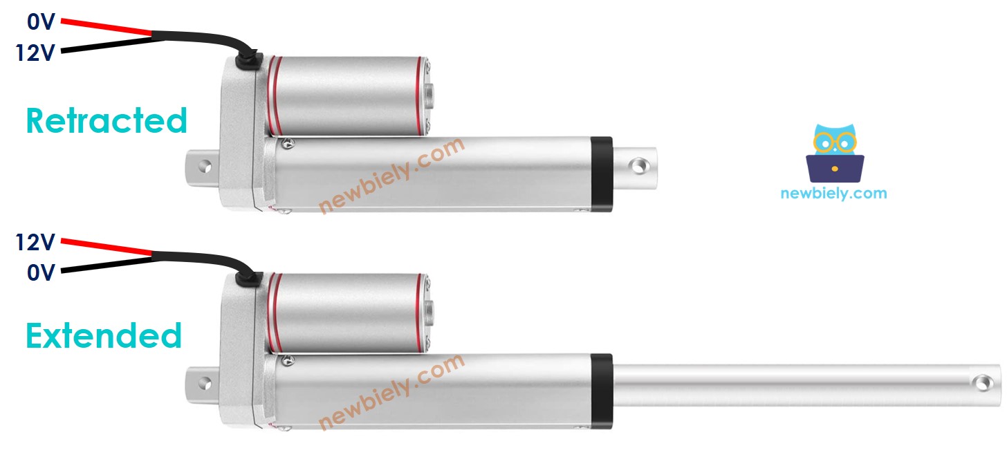
How It Works
For a 12V linear actuator:
- Connect 12V to positive, GND to negative → actuator extends fully at full speed until it reaches its limit.
- Connect 12V to negative, GND to positive → actuator retracts fully at full speed until it reaches its limit.
- Connect both wires to GND → actuator stops.
The Motor Shield Rev3 handles these polarity switches for you. The DIYables_DC_Motor library controls direction and speed — use motor.run(MOTOR_FORWARD, 255) to extend and motor.run(MOTOR_BACKWARD, 255) to retract at full speed. Call motor.brake() to stop.
※ NOTE THAT:
Unlike regular DC motors, linear actuators can hold their position even without power when carrying a load.
If you are not familiar with the Motor Shield Rev3 (pinout, how it works, and how to program it), see the Arduino UNO Q - DC Motor Shield tutorial first.
Wiring Diagram
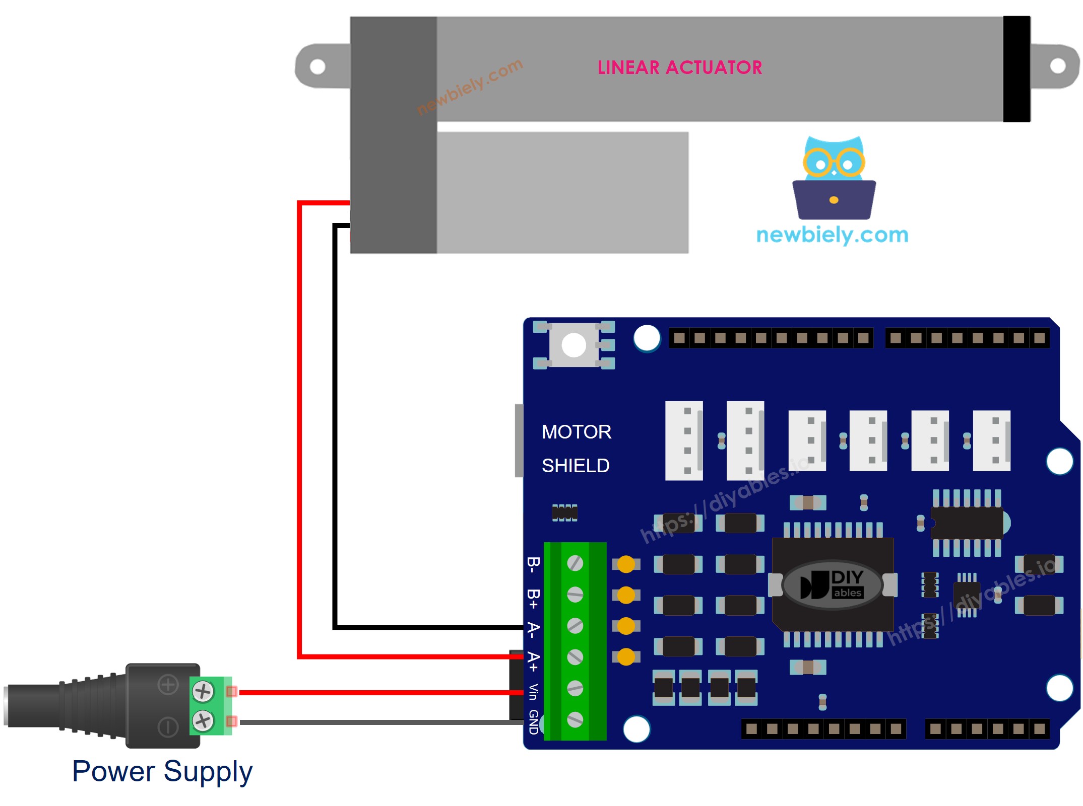
This image is created using Fritzing. Click to enlarge image
MCU Code
The Arduino UNO Q has two processors: the STM32 MCU (handles real-time hardware control) and the Qualcomm MPU (runs Debian Linux). In this section, only the STM32 MCU is programmed — the Linux side stays idle. A later section will show how both processors work together.
The code below extends the actuator for 20 seconds, then retracts it for 20 seconds, repeatedly:
Detailed Instructions
- First time with Arduino UNO Q? Follow the Getting Started with Arduino UNO Q tutorial to get your development environment ready before proceeding.
- Stack the shield: Firmly press the Motor Shield Rev3 onto the Arduino UNO Q headers. Connect the actuator wires to the Channel A screw terminals. Connect the 12V power supply to the shield's power screw terminals.
- Connect: Plug the Arduino UNO Q into your computer with a USB-C cable.
- Open Arduino App Lab: Launch Arduino App Lab and wait until it detects your Arduino UNO Q.
- Create a new App: Click the Create New App button.

- Give the App a name, for example: DIYables_Actuator
- Click Create to confirm.
- You will see a set of folders and files generated inside your new App.

- Find the sketch/sketch.ino file — this is where you will paste the MCU sketch.
- Install the library: Click the Add sketch library button (the open book icon with a + sign) in the left sidebar.

- Search for DIYables_DC_Motor created by DIYables.io and click the Install button.
- Upload: Click the Run button in Arduino App Lab to compile and upload to the STM32.

- Test: The actuator should extend fully, pause, then retract fully, repeatedly.
Linux + MCU Bridge Programming
The Arduino UNO Q has two processors that work together: the MPU (Qualcomm, runs Debian Linux) and the MCU (STM32, runs Zephyr OS with your Arduino sketch). They communicate using RPC via the Arduino_RouterBridge library — never via raw serial ports.
- The Motor Shield Rev3 and actuator are controlled by the MCU (STM32) — the DIYables_DC_Motor library drives the actuator via Channel A.
- The MPU cannot control the actuator directly — it calls Bridge.call("actuator_extend"), Bridge.call("actuator_retract"), or Bridge.call("actuator_stop") on the MCU.
- The MPU has Wi-Fi — because the MPU runs full Debian Linux with Wi-Fi, it can accept Telegram commands to control the actuator remotely.
- Communication: Bridge.call() on the Linux side invokes Bridge.provide_safe() on the MCU side (since motor.run() and motor.brake() use hardware APIs)
- ⚠️ Reserved: /dev/ttyHS1 (Linux) and Serial1 (MCU) are used by the Arduino Router — never open them directly
In short: MPU sends actuator command → MCU drives Motor Shield → actuator extends or retracts.
MCU sketch — actuator control with Bridge:
Python script (Arduino App Lab) — extend, pause, retract, pause cycle:
- Note: Make sure Bridge.begin() is called in the MCU sketch and the sketch is uploaded before running the Python script on the Linux side.
- ⚠️ Warning: Never directly open /dev/ttyHS1 (on Linux) or use Serial1 (on MCU) in your code — these are reserved by the Arduino Router and accessing them will break the Bridge.
Detailed Instructions
- Upload the MCU sketch: Open Arduino App Lab, create a new App, paste the Bridge MCU sketch into sketch/sketch.ino, install both DIYables_DC_Motor and Arduino_RouterBridge libraries, and click Run.
- Add the Python script: Paste the Python code above into the Python tab of the same App.
- Run the App: Click Run — Python extends and retracts the actuator in a cycle.
- Check the console: Open the Console tab → MCU Monitor subtab to see actuator state.
App Lab Console Output
Telegram Integration
Control the actuator remotely via Telegram with /extend, /retract, and /stop commands.
If you do not have a Telegram bot yet, see How to Create a Telegram Bot to get your bot token before continuing.
MCU sketch: Keep the same MCU sketch from the previous Bridge section — no changes needed. Make sure it is already uploaded and running on the STM32 before proceeding.
Python script (Arduino App Lab) — Telegram bot for actuator control:
- Note: Replace YOUR_BOT_TOKEN with the token obtained from @BotFather on Telegram.
- Send /extend, /retract, or /stop to control the actuator.
Detailed Instructions
- Upload the MCU sketch: Use the Bridge MCU sketch from the previous section (upload it first if not already done).
- Paste the Telegram script: Copy the Python code above into the Python tab of your App in Arduino App Lab.
- Set your token: Replace YOUR_BOT_TOKEN in the script with your actual bot token.
- Run the App: Click Run — the bot starts listening for Telegram messages.
- Test it: Send /extend, /retract, and /stop to control the actuator.
App Lab Console Output

ArduinoBot
OpenClaw Integration
You can adapt the OpenClaw to this tutorial by refering the instruction on Arduino Uno Q - OpenClaw Tutorial
Application/Project Ideas
- Automated gate: Extend to open and retract to close a physical gate
- Adjustable desk: Control desk height with Telegram commands
- Solar panel tracker: Tilt a solar panel toward the sun using motion-triggered actuator
- Camera slider: Drive a camera along a linear track for smooth video shots
Challenge Yourself
- Easy: Change the extension and retraction time from 20 seconds to 10 seconds
- Medium: Add a /stop_after_extend Telegram command that extends, waits 10 seconds, then stops automatically
- Advanced: Combine with a limit switch to detect when the actuator reaches its full extent