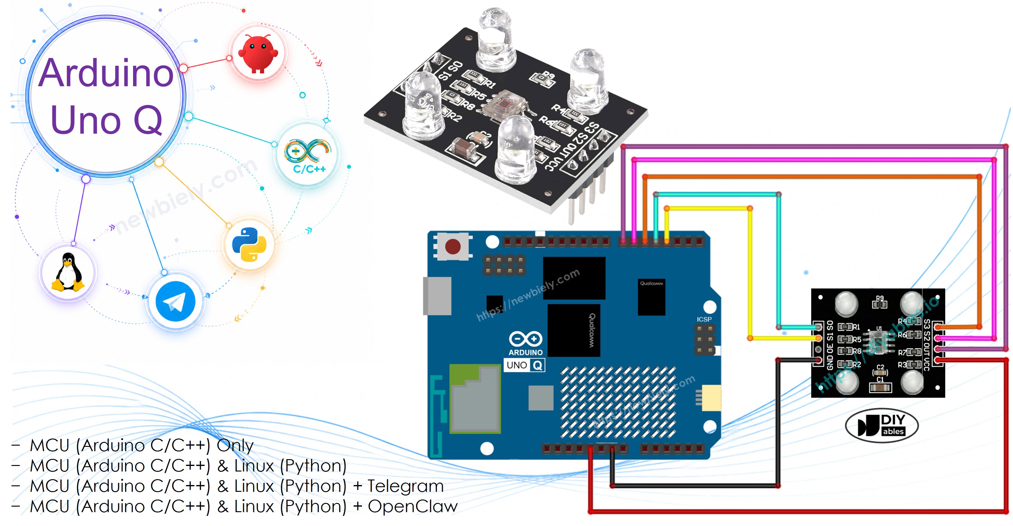
The TCS3200D/TCS230 color recognition sensor detects colors by measuring red, green, and blue light intensity. It outputs a frequency-based signal that you read with pulseIn(), then map to standard 0-255 RGB values after calibration.
In this tutorial, you will learn:
How the TCS3200D/TCS230 color sensor works
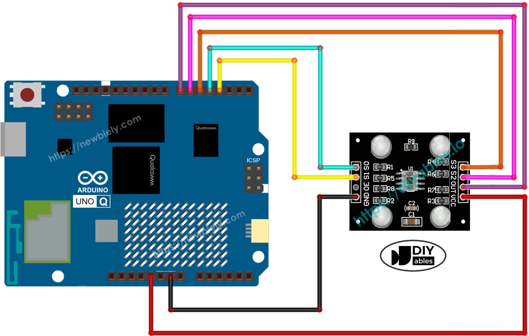
How to wire it to the Arduino UNO Q MCU
How to run the calibration sketch to get accurate readings
How to read RGB values and detect dominant colors
How to use Bridge to expose color data to the Linux side (Python)
How to use Telegram to query RGB values and color name on Arduino UNO Q
How to use OpenClaw on Arduino UNO Q with the color sensor
Disclosure: Some of the links provided in this section are Amazon affiliate links. We may receive a commission for any purchases made through these links at no additional cost to you. Additionally, some of these links are for products from our own brand, DIYables .
Overview of the TCS3200D/TCS230 Color Sensor
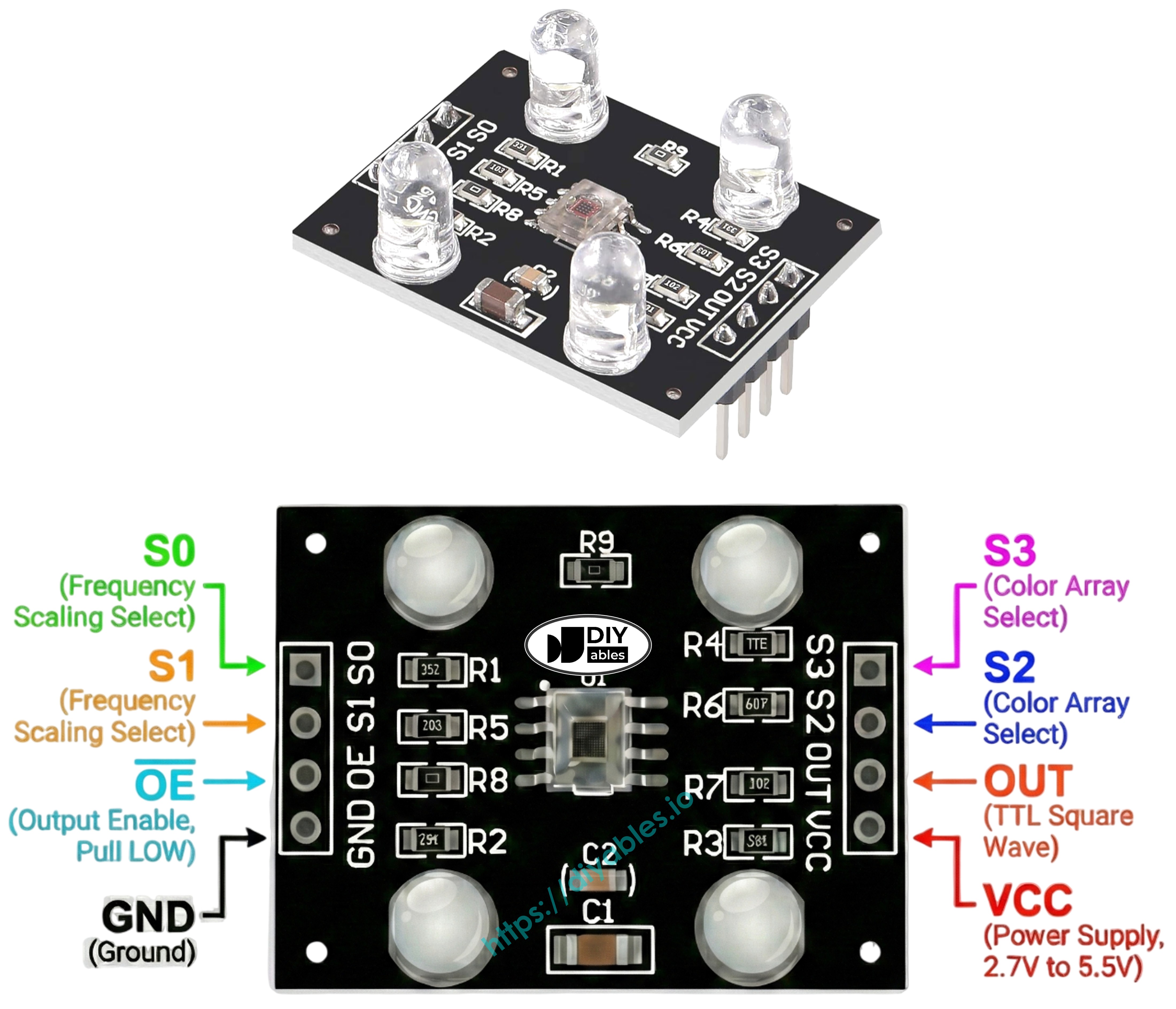
The TCS3200D/TCS230 uses an 8×8 array of photodiodes: 16 red-filtered, 16 green-filtered, 16 blue-filtered, and 16 clear. It converts light intensity into a square-wave frequency on the OUT pin. By switching filters and measuring pulse widths, you get RGB values.
Most modules include white LEDs to illuminate the target object, giving consistent readings in varying ambient light.
Map to 0-255 after calibration (lower PW = brighter = higher value):
int redValue = map(redPW, redMin, redMax, 255, 0);
Arduino UNO Q Code — Calibration
The TCS3200 readings are affected by distance, LED brightness, and ambient light. Run this calibration sketch first to find the minimum and maximum pulse widths for your specific setup.
/* * This Arduino UNO Q code was developed by newbiely.com * * This Arduino UNO Q code is made available for public use without any restriction * * For comprehensive instructions and wiring diagrams, please visit: * https://newbiely.com/tutorials/arduino-uno-q/arduino-uno-q-tcs3200d-tcs230-color-sensor */// TCS3200 Color Sensor - Calibration Sketch// Run this first to find the min/max pulse widths for your environment.// Point the sensor at white, black, and various colored objects.// Note the stable Min and Max values, then enter them into the main sketch.#define S0 4#define S1 3#define S2 6#define S3 5#define sensorOut 7int redPW = 0, greenPW = 0, bluePW = 0;int redMin = 10000, redMax = 0;int greenMin = 10000, greenMax = 0;int blueMin = 10000, blueMax = 0;int getRedPW() {digitalWrite(S2, LOW);digitalWrite(S3, LOW);returnpulseIn(sensorOut, LOW);}int getGreenPW() {digitalWrite(S2, HIGH);digitalWrite(S3, HIGH);returnpulseIn(sensorOut, LOW);}int getBluePW() {digitalWrite(S2, LOW);digitalWrite(S3, HIGH);returnpulseIn(sensorOut, LOW);}voidsetup() {pinMode(S0, OUTPUT);pinMode(S1, OUTPUT);pinMode(S2, OUTPUT);pinMode(S3, OUTPUT);pinMode(sensorOut, INPUT);// Frequency scaling 20%digitalWrite(S0, HIGH);digitalWrite(S1, LOW);Serial.begin(9600);Serial.println("=== TCS3200 Calibration ===");Serial.println("Point the sensor at different objects (white, black, colors).");Serial.println("Min and Max values are tracked automatically.");Serial.println("When values look stable, note them down for the main sketch.");Serial.println("------------------------------------------");}voidloop() { redPW = getRedPW(); delay(200); greenPW = getGreenPW(); delay(200); bluePW = getBluePW(); delay(200);if (redPW < redMin) redMin = redPW;if (redPW > redMax) redMax = redPW;if (greenPW < greenMin) greenMin = greenPW;if (greenPW > greenMax) greenMax = greenPW;if (bluePW < blueMin) blueMin = bluePW;if (bluePW > blueMax) blueMax = bluePW;Serial.print("Red PW = "); Serial.print(redPW);Serial.print(" - Green PW = "); Serial.print(greenPW);Serial.print(" - Blue PW = "); Serial.println(bluePW);Serial.print(" Min -> R:"); Serial.print(redMin);Serial.print(" G:"); Serial.print(greenMin);Serial.print(" B:"); Serial.println(blueMin);Serial.print(" Max -> R:"); Serial.print(redMax);Serial.print(" G:"); Serial.print(greenMax);Serial.print(" B:"); Serial.println(blueMax);Serial.println("------------------------------------------");}
Connect: Wire the color sensor to the Arduino UNO Q MCU as shown in the wiring diagram.
Open Arduino App Lab: Launch Arduino App Lab and wait until it detects your Arduino UNO Q.
Create a new App: Click the Create New App button.
Give the App a name, for example: ColorSensorCalibration
Click Create to confirm.
Paste the sketch: Copy the calibration code above and paste it into sketch/sketch.ino.
Upload: Click the Run button in Arduino App Lab.
Move the sensor over different objects: a white object, a black object, and some colored objects.
Watch the Min and Max values stabilize after 10–20 seconds — note them down.
App Lab Console Output
DIYables_Apps
Stop
sketch.ino
1#include"Arduino_RouterBridge.h"
Serial Monitor
Python
Message (Enter to send a message to "Newbiely" on usb(2820070321))
New Line
9600 baud
[2026-04-29 09:00:00] === TCS3200 Calibration ===
[2026-04-29 09:00:00] Point the sensor at different objects (white, black, colors).
[2026-04-29 09:00:00] Min and Max values are tracked automatically.
[2026-04-29 09:00:00] When values look stable, note them down for the main sketch.
[2026-04-29 09:00:00] ------------------------------------------
[2026-04-29 09:00:01] Red PW = 42 - Green PW = 55 - Blue PW = 60
[2026-04-29 09:00:01] Min -> R:42 G:55 B:60
[2026-04-29 09:00:01] Max -> R:42 G:55 B:60
[2026-04-29 09:00:01] ------------------------------------------
[2026-04-29 09:00:02] Red PW = 210 - Green PW = 185 - Blue PW = 172
[2026-04-29 09:00:02] Min -> R:42 G:55 B:60
[2026-04-29 09:00:02] Max -> R:210 G:185 B:172
[2026-04-29 09:00:02] ------------------------------------------
From the output above, your calibration values are:
redMin = 42, redMax = 210
greenMin = 55, greenMax = 185
blueMin = 60, blueMax = 172
Arduino UNO Q Code — Read RGB Values
Now update the six calibration variables at the top with your actual values and upload this main sketch to read accurate RGB values.
/* * This Arduino UNO Q code was developed by newbiely.com * * This Arduino UNO Q code is made available for public use without any restriction * * For comprehensive instructions and wiring diagrams, please visit: * https://newbiely.com/tutorials/arduino-uno-q/arduino-uno-q-tcs3200d-tcs230-color-sensor */// TCS3200 Color Sensor - Read RGB Values// IMPORTANT: Run the calibration sketch first and replace the 0 values below// with your actual calibration numbers.#define S0 4#define S1 3#define S2 6#define S3 5#define sensorOut 7// Calibration values — replace with your values from the calibration sketchint redMin = 0; // Red minimum pulse widthint redMax = 0; // Red maximum pulse widthint greenMin = 0; // Green minimum pulse widthint greenMax = 0; // Green maximum pulse widthint blueMin = 0; // Blue minimum pulse widthint blueMax = 0; // Blue maximum pulse widthint redPW = 0, greenPW = 0, bluePW = 0;int redValue = 0, greenValue = 0, blueValue = 0;int getRedPW() {digitalWrite(S2, LOW);digitalWrite(S3, LOW);returnpulseIn(sensorOut, LOW);}int getGreenPW() {digitalWrite(S2, HIGH);digitalWrite(S3, HIGH);returnpulseIn(sensorOut, LOW);}int getBluePW() {digitalWrite(S2, LOW);digitalWrite(S3, HIGH);returnpulseIn(sensorOut, LOW);}voidsetup() {pinMode(S0, OUTPUT);pinMode(S1, OUTPUT);pinMode(S2, OUTPUT);pinMode(S3, OUTPUT);pinMode(sensorOut, INPUT);// Frequency scaling 20%digitalWrite(S0, HIGH);digitalWrite(S1, LOW);Serial.begin(9600);Serial.println("Arduino UNO Q TCS3200 Color Sensor ready");}voidloop() { redPW = getRedPW(); delay(200); greenPW = getGreenPW(); delay(200); bluePW = getBluePW(); delay(200);// Map pulse width to 0-255 (lower PW = more light = higher value) redValue = map(redPW, redMin, redMax, 255, 0); greenValue = map(greenPW, greenMin, greenMax, 255, 0); blueValue = map(bluePW, blueMin, blueMax, 255, 0);Serial.print("Red = "); Serial.print(redValue);Serial.print(" - Green = "); Serial.print(greenValue);Serial.print(" - Blue = "); Serial.println(blueValue);}
Create a new App (or update the previous one), paste the code, and click Run.
Point the sensor at different colored objects and observe the Serial Monitor.
App Lab Console Output
DIYables_Apps
Stop
sketch.ino
1#include"Arduino_RouterBridge.h"
Serial Monitor
Python
Message (Enter to send a message to "Newbiely" on usb(2820070321))
New Line
9600 baud
[2026-04-29 09:00:01] Arduino UNO Q TCS3200 Color Sensor ready
[2026-04-29 09:00:02] Red = 210 - Green = 35 - Blue = 20
[2026-04-29 09:00:03] Red = 25 - Green = 200 - Blue = 40
[2026-04-29 09:00:04] Red = 30 - Green = 45 - Blue = 215
[2026-04-29 09:00:05] Red = 225 - Green = 220 - Blue = 218
Bridge: Linux + MCU
This section shows how both processors of the Arduino UNO Q work together so the Linux side can continuously read color data via Bridge:
The color sensor is connected to the MCU — the MCU reads RGB values every 600 ms and caches them
The MPU cannot read the sensor directly — it calls Bridge functions to get RGB or color name
The MPU has Wi-Fi — running full Debian Linux, it can respond to Telegram commands with live color readings
Arduino_RouterBridge enables RPC communication between the two processors
⚠️ /dev/ttyHS1 (Linux) and Serial1 (MCU) are RESERVED by the router — never open them in user code
The MCU loop reads R, G, B channels every 600 ms and caches the values. Bridge callbacks serve the cached values instantly, without blocking.
MCU Code (Bridge)
/* * This Arduino UNO Q code was developed by newbiely.com * * This Arduino UNO Q code is made available for public use without any restriction * * For comprehensive instructions and wiring diagrams, please visit: * https://newbiely.com/tutorials/arduino-uno-q/arduino-uno-q-tcs3200d-tcs230-color-sensor */#include"Arduino_RouterBridge.h"#define S0 4#define S1 3#define S2 6#define S3 5#define sensorOut 7// Calibration values — replace with your values from the calibration sketchint redMin = 42;int redMax = 210;int greenMin = 55;int greenMax = 185;int blueMin = 60;int blueMax = 172;// Cached RGB valuesint cached_red = 0;int cached_green = 0;int cached_blue = 0;unsignedlong last_read_ms = 0;constunsignedlong READ_INTERVAL = 600;int getRedPW() {digitalWrite(S2, LOW);digitalWrite(S3, LOW);returnpulseIn(sensorOut, LOW);}int getGreenPW() {digitalWrite(S2, HIGH);digitalWrite(S3, HIGH);returnpulseIn(sensorOut, LOW);}int getBluePW() {digitalWrite(S2, LOW);digitalWrite(S3, HIGH);returnpulseIn(sensorOut, LOW);}String get_rgb(String arg) {return"R:" + String(cached_red) + " G:" + String(cached_green) + " B:" + String(cached_blue);}String get_color(String arg) {int r = cached_red;int g = cached_green;int b = cached_blue;// Detect dominant colorif (r > 200 && g > 200 && b > 200) return"white";if (r < 50 && g < 50 && b < 50) return"black";if (r > g && r > b) return"red";if (g > r && g > b) return"green";if (b > r && b > g) return"blue";return"unknown";}voidsetup() {Bridge.begin(); Monitor.begin();pinMode(S0, OUTPUT);pinMode(S1, OUTPUT);pinMode(S2, OUTPUT);pinMode(S3, OUTPUT);pinMode(sensorOut, INPUT);// Frequency scaling 20%digitalWrite(S0, HIGH);digitalWrite(S1, LOW);Bridge.provide("get_rgb", get_rgb);Bridge.provide("get_color", get_color); Monitor.println("Arduino UNO Q TCS3200 Color Sensor Bridge ready");}voidloop() {unsignedlongnow = millis();if (now - last_read_ms >= READ_INTERVAL) { last_read_ms = now;int redPW = getRedPW(); delay(200);int greenPW = getGreenPW(); delay(200);int bluePW = getBluePW(); delay(200); cached_red = constrain(map(redPW, redMin, redMax, 255, 0), 0, 255); cached_green = constrain(map(greenPW, greenMin, greenMax, 255, 0), 0, 255); cached_blue = constrain(map(bluePW, blueMin, blueMax, 255, 0), 0, 255); }}
Python Code (Bridge)
"""This Arduino UNO Q script was developed by newbiely.comThis Arduino UNO Q script is made available for public use without any restrictionFor comprehensive instructions and wiring diagrams, please visit:https://newbiely.com/tutorials/arduino-uno-q/arduino-uno-q-tcs3200d-tcs230-color-sensor"""from arduino.app_utils import *import timedef loop(): rgb = Bridge.call("get_rgb") color = Bridge.call("get_color")print(f"Color: {color} | {rgb}") time.sleep(1)App.run(user_loop=loop)
Detailed Instructions
Connect: Wire the color sensor to the Arduino UNO Q as shown in the wiring diagram.
Open Arduino App Lab and create a new App named ColorSensorBridge.
Update calibration values in the MCU Bridge code (redMin, redMax, etc.) with your values from the calibration sketch.
Paste the MCU sketch into sketch/sketch.ino.
Paste the Python code into the Python file.
Install the library: Click the Add sketch library button (the open book icon with a + sign) in the left sidebar.
Search for Arduino_RouterBridge created by Arduino and click the Install button.
My Apps/DIYables Apps
Run
Bricks
No bricks added...
Sketch Libraries
No sketch libra...
Files
python
sketch
.gitignore
README.md
app.yaml
sketch.ino
Add sketch library
Arduino_RouterBridge
Arduino_RouterBridgeArduino
This library provides a simple RPC bridge for Arduino UNO Q boards, allowing communication between the board and other devices using MsgPack serialization.
0.4.1
Install
More Info
Upload: Click the Run button.
Point the sensor at different colored objects — watch the Python console update every second.
App Lab Console Output
DIYables_Apps
Stop
sketch.ino
1#include"Arduino_RouterBridge.h"
Serial Monitor
Python
Message (Enter to send a message to "Newbiely" on usb(2820070321))
New Line
9600 baud
[2026-04-29 09:00:01] Arduino UNO Q TCS3200 Color Sensor Bridge ready
DIYables_Apps
Stop
sketch.ino
1#include"Arduino_RouterBridge.h"
Serial Monitor
Python
[2026-04-29 09:00:02] Color: red | R:215 G:30 B:25
[2026-04-29 09:00:03] Color: green | R:28 G:205 B:38
[2026-04-29 09:00:04] Color: blue | R:22 G:40 B:218
[2026-04-29 09:00:05] Color: white | R:228 G:222 B:220
[2026-04-29 09:00:06] Color: black | R:12 G:10 B:8
Telegram
Query the color sensor remotely via Telegram commands on the Arduino UNO Q.
MCU sketch: Keep the same MCU sketch from the previous Bridge section.
Python Code (Telegram)
"""This Arduino UNO Q script was developed by newbiely.comThis Arduino UNO Q script is made available for public use without any restrictionFor comprehensive instructions and wiring diagrams, please visit:https://newbiely.com/tutorials/arduino-uno-q/arduino-uno-q-tcs3200d-tcs230-color-sensor"""from arduino.app_utils import *import requestsimport timeTELEGRAM_BOT_TOKEN = "YOUR_TELEGRAM_BOT_TOKEN"CHAT_ID = "YOUR_CHAT_ID"last_update_id = 0def get_updates():global last_update_id url = f"https://api.telegram.org/bot{TELEGRAM_BOT_TOKEN}/getUpdates" params = {"offset": last_update_id + 1, "timeout": 5}try: response = requests.get(url, params=params, timeout=10) data = response.json()if data["ok"]:return data["result"]exceptExceptionas e:print(f"Error getting updates: {e}")return []def send_message(chat_id, text): url = f"https://api.telegram.org/bot{TELEGRAM_BOT_TOKEN}/sendMessage" payload = {"chat_id": chat_id, "text": text}try: requests.post(url, data=payload, timeout=10)exceptExceptionas e:print(f"Error sending message: {e}")def loop(): updates = get_updates()for update in updates: last_update_id = update["update_id"]if"message"notin update:continue message = update["message"] chat_id = message["chat"]["id"] text = message.get("text", "").strip()print(f"Received: {text}")if text == "/start": send_message(chat_id,"Arduino UNO Q Color Sensor Bot\n""/rgb - Read RGB values (0-255)\n""/color - Detect dominant color")elif text == "/rgb": result = Bridge.call("get_rgb") send_message(chat_id, f"RGB values: {result}")elif text == "/color": result = Bridge.call("get_color") send_message(chat_id, f"Detected color: {result}")else: send_message(chat_id, "Unknown command. Send /start for help.") time.sleep(0.5)App.run(user_loop=loop)
Detailed Instructions
Replace YOUR_TELEGRAM_BOT_TOKEN with your actual Telegram bot token from BotFather.
Replace YOUR_CHAT_ID with your Telegram chat ID.
Paste this Python code into your App's Python file (keep the same MCU sketch).
Click the Run button and test with /rgb and /color commands.
You can adapt the OpenClaw to this tutorial by refering the instruction on Arduino Uno Q - OpenClaw Tutorial
Project Ideas
You can build many useful projects with the TCS3200 color sensor and Arduino UNO Q:
Color Sorter Machine: Detect the color of objects on a conveyor belt via Bridge — have the MCU trigger a servo to redirect each object to the correct bin based on its detected color
Remote Color Logger: Log detected colors and RGB values to a CSV file on Linux every 5 seconds — use a Telegram /report command to get the last 10 readings with timestamps
Color-Activated Alert: Use Telegram to define a target color — when the sensor detects that exact color, send an instant Telegram notification (e.g., for quality control on a production line)
Plant Health Monitor: Point the sensor at plant leaves — track the green channel value daily to detect early yellowing or discoloration, and send a Telegram alert if the green value drops below a threshold
Interactive Color Game: Send a Telegram message like "Show me BLUE in 10 seconds" — the MCU reads the color and Python replies with whether the player showed the correct color before the timer
Challenge Yourself
Ready to go further with the TCS3200 color sensor on Arduino UNO Q? Try these challenges:
Easy: Add a /history Telegram command that returns the last 5 detected colors with timestamps stored in a Python list — useful for reviewing recent readings without checking the console.
Medium: Implement averaging: instead of caching a single reading, have the MCU read each R/G/B channel 3 times and return the average — this smooths out noise and improves color detection accuracy.
Advanced: Build a color learning system: add /learn red, /learn green, /learn blue Telegram commands that capture the current RGB reading and store it as the reference for that color — then use these stored references for color matching instead of hardcoded thresholds.
Please feel free to share the link of this tutorial. However, Please do not use our content on any other websites. We invested a lot of effort and time to create the content, please respect our work!