Arduino UNO Q - Buzzer
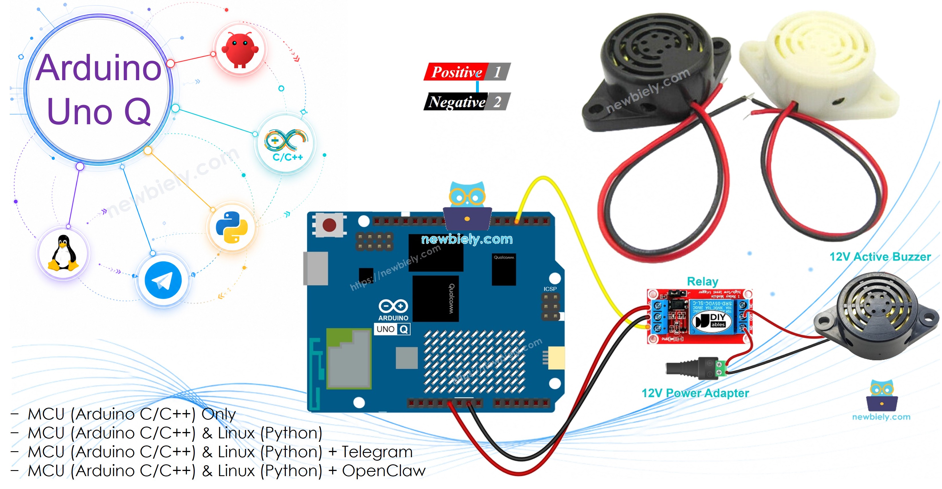
A 12V active buzzer produces a loud sound — ideal for alarms and alerts. Because it requires 12V, it cannot be powered directly from the Arduino UNO Q. Instead, a relay acts as a switch that the Arduino controls. In this tutorial, you will learn how to wire a 12V active buzzer to Arduino UNO Q via a relay and control it locally and remotely via Telegram.
Hardware Preparation
Or you can buy the following kits:
| 1 | × | DIYables Sensor Kit (18 sensors/displays) |
Additionally, some of these links are for products from our own brand, DIYables .
Overview of 12V Active Buzzer
A 12V active buzzer produces a loud continuous sound when 12V is applied — no frequency signal needed.
Pinout

- Positive (+) pin (red): Connect to 12V power supply (via relay)
- Negative (−) pin (black): Connect to GND of the 12V power supply
How to Control It with Arduino UNO Q
Because the buzzer requires 12V and Arduino UNO Q outputs 3.3V, a relay is needed:
- The Arduino UNO Q controls the relay coil (3.3V-compatible signal)
- The relay switches the 12V line to the buzzer ON or OFF
- If you are unfamiliar with relays, see Arduino UNO Q - Relay tutorial first
Wiring Diagram
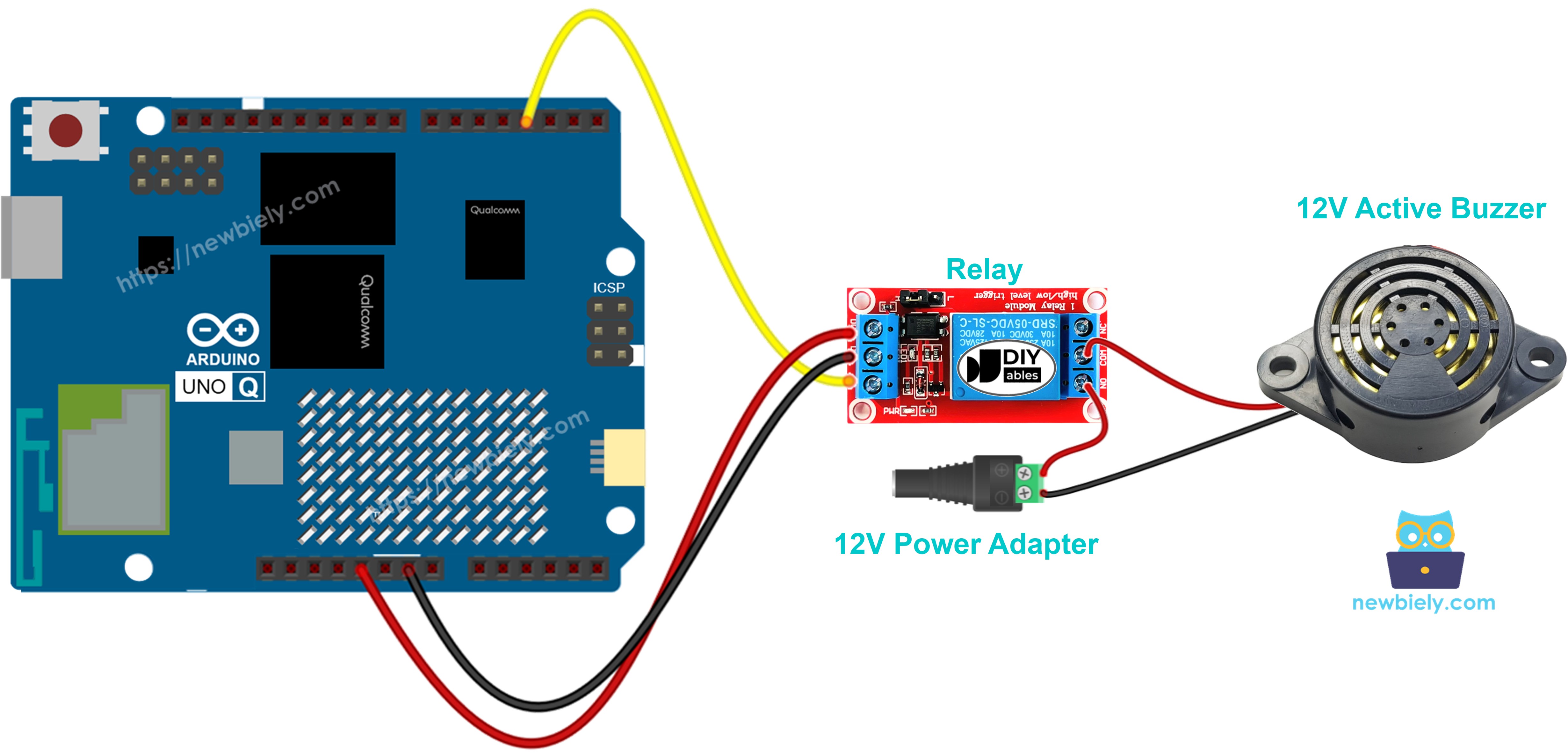
This image is created using Fritzing. Click to enlarge image
MCU Code
The Arduino UNO Q has two processors: the STM32 MCU (handles real-time hardware control) and the Qualcomm MPU (runs Debian Linux). In this section, only the STM32 MCU is programmed — the Linux side stays idle. A later section will show how both processors work together.
The code turns the 12V buzzer ON for 2 seconds and OFF for 5 seconds, repeating continuously:
Detailed Instructions
- First time with Arduino UNO Q? Follow the Getting Started with Arduino UNO Q tutorial to get your development environment ready before proceeding.
- Wire the components: Connect the relay signal pin to pin 3, wire the relay to the 12V buzzer and 12V power supply as shown in the diagram.
- Connect: Plug the Arduino UNO Q into your computer with a USB-C cable.
- Open Arduino App Lab: Launch Arduino App Lab and wait until it detects your Arduino UNO Q.
- Create a new App: Click the Create New App button.

- Give the App a name, for example: DIYables_Buzzer12V
- Click Create to confirm.
- You will see a set of folders and files generated inside your new App.

- Find the sketch/sketch.ino file — this is where you will paste the MCU sketch.
- Install the library: Click the Add sketch library button (the open book icon with a + sign) in the left sidebar.

- Search for Arduino_RouterBridge created by Arduino and click the Install button.
- Upload: Click the Run button in Arduino App Lab to compile and upload to the STM32.

- Listen: The buzzer turns ON for 2 seconds, then OFF for 5 seconds, repeating continuously.
Linux + MCU Bridge Programming
The Arduino UNO Q has two processors that work together: the MPU (Qualcomm, runs Debian Linux) and the MCU (STM32, runs Zephyr OS with your Arduino sketch). They communicate using RPC via the Arduino_RouterBridge library — never via raw serial ports.
- The relay is connected to the MCU (STM32) — wired to a digital output pin. The MCU drives the relay HIGH/LOW to control the 12V buzzer.
- The MPU cannot control the relay directly — it must call a function on the MCU via Bridge.call() to turn the buzzer ON or OFF.
- The MPU has Wi-Fi — because the MPU runs full Debian Linux with Wi-Fi, it can receive Telegram commands and remotely trigger the buzzer.
- Communication: Bridge.call() on the Linux side invokes Bridge.provide_safe() functions on the MCU side (since digitalWrite() is a hardware API)
- ⚠️ Reserved: /dev/ttyHS1 (Linux) and Serial1 (MCU) are used by the Arduino Router — never open them directly
In short: MPU sends on/off command → MCU drives relay → relay switches 12V buzzer.
MCU sketch — relay-controlled buzzer with Bridge and Monitor output:
Python script (Arduino App Lab) — control buzzer from Linux:
- Note: Make sure Bridge.begin() is called in the MCU sketch and the sketch is uploaded before running the Python script on the Linux side.
- ⚠️ Warning: Never directly open /dev/ttyHS1 (on Linux) or use Serial1 (on MCU) in your code — these are reserved by the Arduino Router and accessing them will break the Bridge.
Detailed Instructions
- Upload the MCU sketch: Open Arduino App Lab, create a new App, paste the Bridge MCU sketch into sketch/sketch.ino, install the Arduino_RouterBridge library, and click Run.
- Add the Python script: Paste the Python code above into the Python tab of the same App.
- Run the App: Click Run — Python cycles the buzzer ON for 2 s and OFF for 5 s automatically.
- Check the console: Open the Console tab → MCU Monitor subtab to see "Buzzer ON" and "Buzzer OFF" messages.
App Lab Console Output
Telegram Integration
Control the 12V buzzer remotely from anywhere via Telegram.
If you do not have a Telegram bot yet, see How to Create a Telegram Bot to get your bot token before continuing.
MCU sketch: Keep the same MCU sketch from the previous Bridge section — no changes needed. Make sure it is already uploaded and running on the STM32 before proceeding.
Python script (Arduino App Lab) — Telegram bot for 12V buzzer control:
- Note: Replace YOUR_BOT_TOKEN with the token obtained from @BotFather on Telegram.
- Send /on to turn the buzzer ON.
- Send /off to turn the buzzer OFF.
Detailed Instructions
- Upload the MCU sketch: Use the Bridge MCU sketch from the previous section (upload it first if not already done).
- Paste the Telegram script: Copy the Python code above into the Python tab of your App in Arduino App Lab.
- Set your token: Replace YOUR_BOT_TOKEN in the script with your actual bot token.
- Run the App: Click Run — the bot starts listening for Telegram messages.
- Test it: Send /on — hear the buzzer turn on. Send /off — confirm it stops.
App Lab Console Output

ArduinoBot
OpenClaw Integration
You can adapt the OpenClaw to this tutorial by refering the instruction on Arduino Uno Q - OpenClaw Tutorial
Application/Project Ideas
- Remote alarm: Trigger a loud 12V alarm from anywhere via Telegram when a security event occurs
- Timed alert: Use the MPU's Linux clock to sound the buzzer at a scheduled time
- Door security alarm: Pair with a motion sensor — sound the buzzer when motion is detected unexpectedly
- Process completion alert: Sound the buzzer when a long-running process (e.g., 3D print, oven timer) finishes
- Perimeter warning: Use multiple relay channels to control several buzzers in different zones
Challenge Yourself
- Easy: Add a /status command that reports whether the buzzer is currently ON or OFF
- Medium: Add a /beep <count> Telegram command that beeps the buzzer N times with a 1-second interval
- Advanced: Build a Telegram-controlled countdown alarm — schedule a buzzer trigger time from Telegram and have the MPU sound it automatically