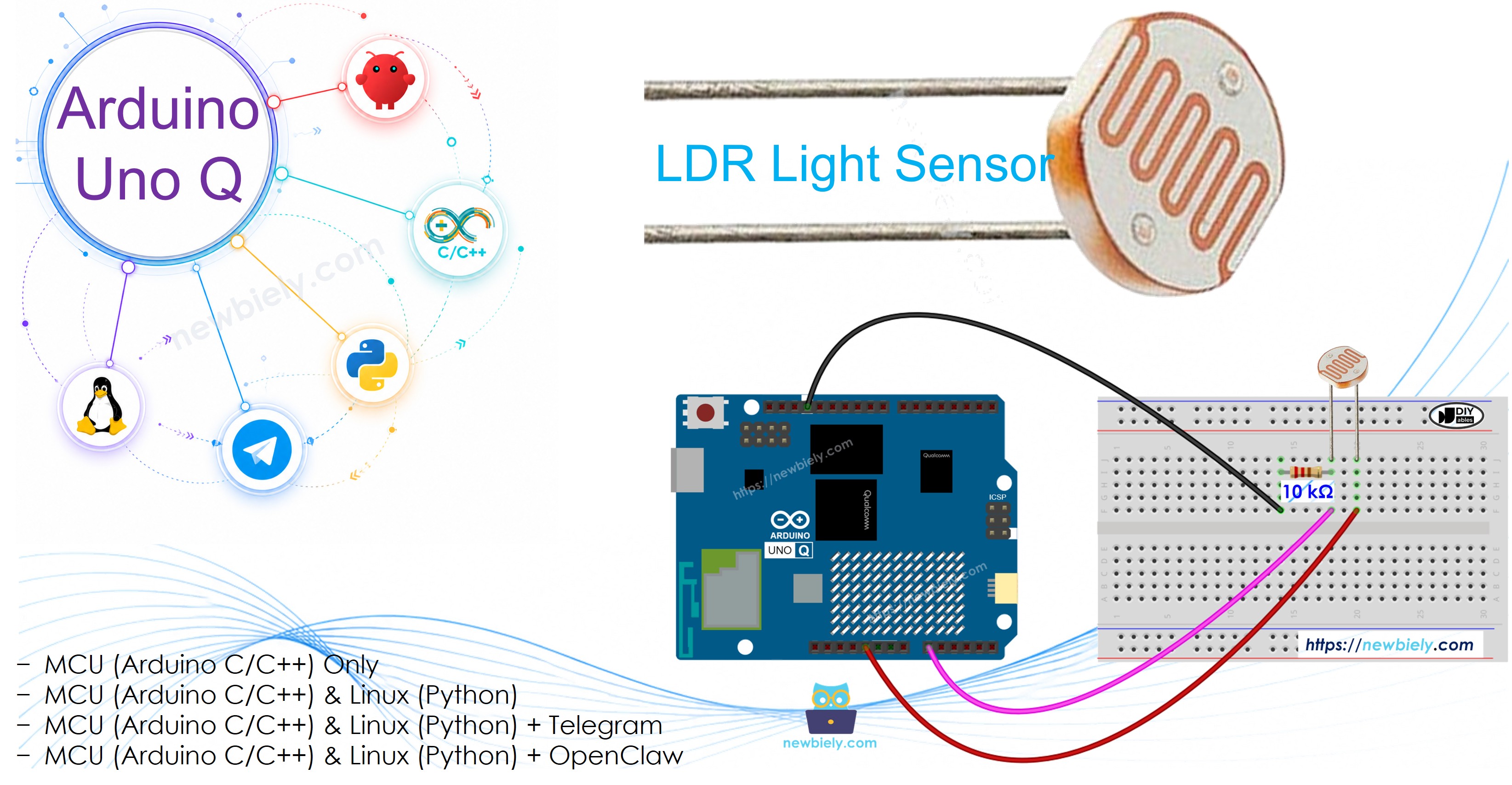
Arduino UNO Q - Light Sensor
This tutorial shows you how to use an LDR light sensor with the Arduino UNO Q. In detail, you will learn:
- How an LDR light sensor works
- How to connect a light sensor to the Arduino UNO Q
- How to write a program to read the value from the light sensor
Hardware Preparation
Or you can buy the following kits:
| 1 | × | DIYables Sensor Kit (18 sensors/displays) |
Additionally, some of these links are for products from our own brand, DIYables .
The LDR light sensor is very affordable, but it requires a resistor for wiring, which can make the setup more complex. To simplify the wiring, you can use an LDR light sensor module as an alternative.
Overview of Light Sensor
This tutorial uses a light sensor known as a photoresistor, also referred to as a Light-Dependent Resistor (LDR) or photocell. It is used to find and measure how bright the surrounding light is.
Pinout
A photoresistor has two pins. Because it is a type of resistor, we do not need to identify these pins separately. They are the same.
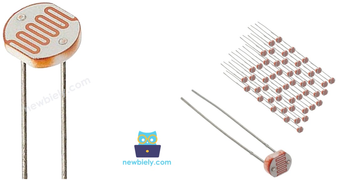
How It Works
A photoresistor is a special type of resistor that changes its resistance based on the amount of light it detects. When there is a lot of light, the resistance becomes very low. When there is little or no light, the resistance becomes very high. By measuring the resistance of the photoresistor, we can determine how bright or dark the surrounding light is.
WARNING
The light sensor value shows a rough idea of how bright the light is, but it does not give the exact amount of light. Use it only in situations where you do not need very accurate measurements.
Arduino UNO Q - Light Sensor
The Arduino UNO Q STM32 MCU has a 12-bit ADC with a 3.3V reference. Analog input pins A0–A5 convert voltage (0 V to 3.3 V) into values between 0 and 4095.
By connecting a pin of the photoresistor to an analog input pin of the Arduino UNO Q, we can read the analog value using the analogRead() function to determine relative light levels.
※ NOTE THAT:
The Arduino UNO Q uses a 12-bit ADC (0–4095) with a 3.3V reference — unlike the Arduino UNO R4 which uses a 14-bit ADC, or traditional Uno boards which use 10-bit (0–1023). Always scale your thresholds accordingly.
Wiring Diagram
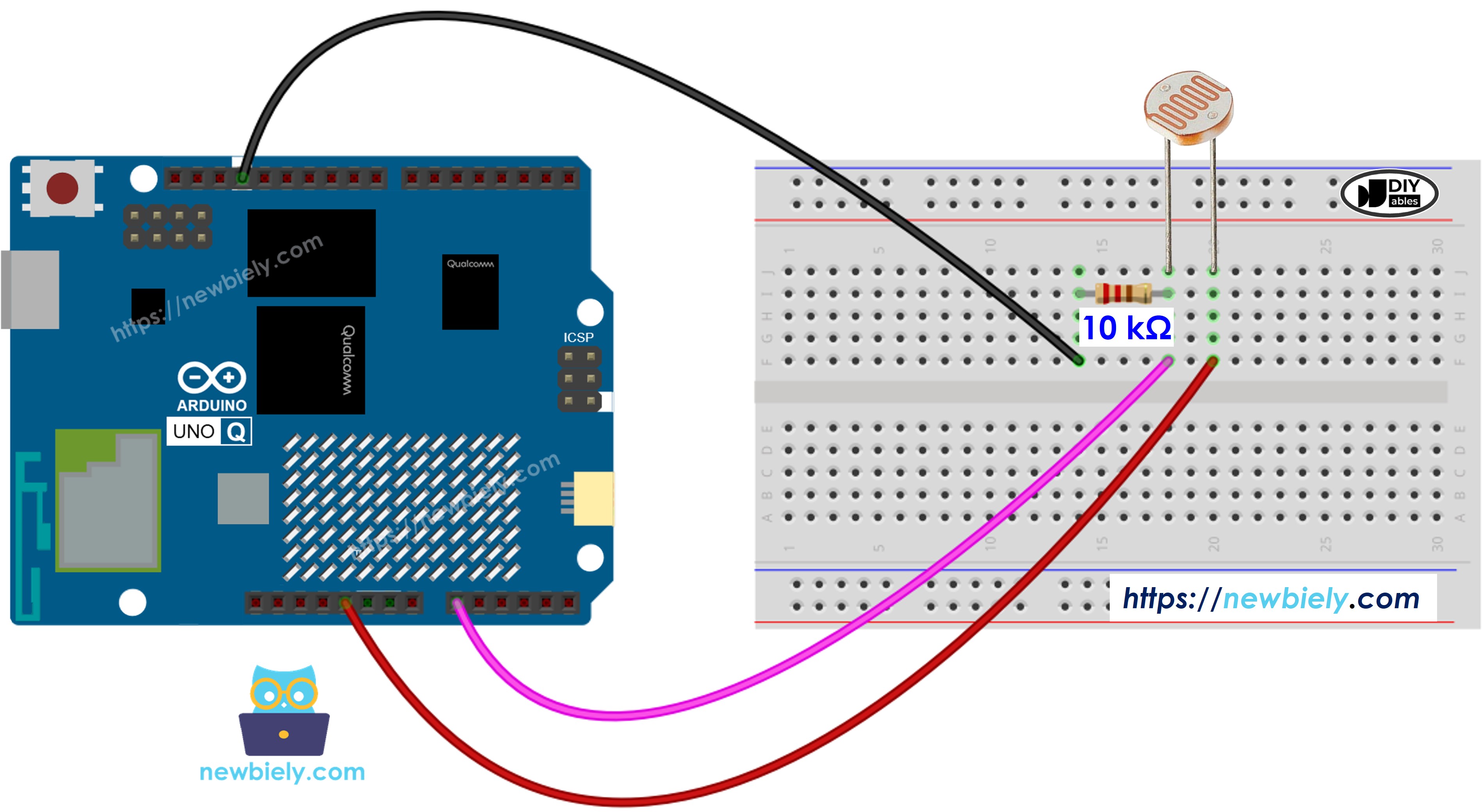
This image is created using Fritzing. Click to enlarge image
MCU Code
The Arduino UNO Q has two processors: the STM32 MCU (handles real-time hardware control) and the Qualcomm MPU (runs Debian Linux). In this section, only the STM32 MCU is programmed — the Linux side stays idle. A later section will show how both processors work together.
The following code reads the ADC value from the photocell every 500 ms:
※ NOTE THAT:
The Arduino UNO Q MCU uses a 12-bit ADC (values 0–4095). Light level thresholds are scaled accordingly: Dark < 40, Dim < 800, Light < 2000, Bright < 3200, Very bright ≥ 3200.
Detailed Instructions
- First time with Arduino UNO Q? Follow the Getting Started with Arduino UNO Q tutorial to get your development environment ready before proceeding.
- Wire the components: Connect the photoresistor and 10 kΩ resistor in a voltage divider to pin A0 as shown in the diagram.
- Connect: Plug the Arduino UNO Q into your computer with a USB-C cable.
- Open Arduino App Lab: Launch Arduino App Lab and wait until it detects your Arduino UNO Q.
- Create a new App: Click the Create New App button.

- Give the App a name, for example: DIYables_LightSensor
- Click Create to confirm.
- You will see a set of folders and files generated inside your new App.

- Find the sketch/sketch.ino file — this is where you will paste the MCU sketch.
- Install the library: Click the Add sketch library button (the open book icon with a + sign) in the left sidebar.

- Search for Arduino_RouterBridge created by Arduino and click the Install button.
- Upload: Click the Run button in Arduino App Lab to compile and upload to the STM32.

- Test: Shine a light at the sensor or cover it with your hand, then use the Bridge section below to read the values via Monitor.
Linux + MCU Bridge Programming
The Arduino UNO Q has two processors that work together: the MPU (Qualcomm, runs Debian Linux) and the MCU (STM32, runs Zephyr OS with your Arduino sketch). They communicate using RPC via the Arduino_RouterBridge library — never via raw serial ports.
- The light sensor is connected to the MCU (STM32) — the photoresistor voltage divider feeds analog pin A0 on the STM32.
- The MPU cannot read A0 directly — it must call a function on the MCU via Bridge.call() to request the sensor reading.
- The MPU has Wi-Fi — because the MPU runs full Debian Linux with Wi-Fi, it can receive Telegram commands and send sensor readings remotely.
- Communication: Bridge.call() on the Linux side invokes Bridge.provide() functions on the MCU side (reading analog is safe — no hardware GPIO write needed)
- ⚠️ Reserved: /dev/ttyHS1 (Linux) and Serial1 (MCU) are used by the Arduino Router — never open them directly
In short: MPU requests reading → MCU reads ADC → MCU prints result to Monitor.
MCU sketch — light sensor reading with Bridge and Monitor output:
Python script (Arduino App Lab) — request readings from Linux every second:
- Note: Make sure Bridge.begin() is called in the MCU sketch and the sketch is uploaded before running the Python script on the Linux side.
- ⚠️ Warning: Never directly open /dev/ttyHS1 (on Linux) or use Serial1 (on MCU) in your code — these are reserved by the Arduino Router and accessing them will break the Bridge.
Detailed Instructions
- Upload the MCU sketch: Open Arduino App Lab, create a new App, paste the Bridge MCU sketch into sketch/sketch.ino, install the Arduino_RouterBridge library, and click Run.
- Add the Python script: Paste the Python code above into the Python tab of the same App.
- Run the App: Click Run — Python requests a light reading every second.
- Shine light / cover sensor: See the values change in the MCU Monitor.
- Check the console: Open the Console tab → MCU Monitor subtab to see the analog readings.
App Lab Console Output
Telegram Integration
Read the light sensor remotely from anywhere via Telegram.
If you do not have a Telegram bot yet, see How to Create a Telegram Bot to get your bot token before continuing.
MCU sketch: Keep the same MCU sketch from the previous Bridge section — no changes needed. Make sure it is already uploaded and running on the STM32 before proceeding.
Python script (Arduino App Lab) — Telegram bot for light sensor reading:
- Note: Replace YOUR_BOT_TOKEN with the token obtained from @BotFather on Telegram.
- Send /read to request the current light sensor reading.
- The reading will appear in the MCU Monitor (Console → MCU Monitor tab).
Detailed Instructions
- Upload the MCU sketch: Use the Bridge MCU sketch from the previous section (upload it first if not already done).
- Paste the Telegram script: Copy the Python code above into the Python tab of your App in Arduino App Lab.
- Set your token: Replace YOUR_BOT_TOKEN in the script with your actual bot token.
- Run the App: Click Run — the bot starts listening for Telegram messages.
- Test it: Send /read — the bot replies with the sensor ADC value and light level.
App Lab Console Output

ArduinoBot
OpenClaw Integration
You can adapt the OpenClaw to this tutorial by refering the instruction on Arduino Uno Q - OpenClaw Tutorial
Application/Project Ideas
- Automatic night light: Read light level on the MPU and turn on an LED strip via Telegram/Bridge when it gets dark
- Smart curtain controller: Use light level to automatically open or close curtains via a servo motor
- Plant light monitor: Periodically check light level and send a Telegram alert when plants need more light
- Security lighting: Trigger an alarm or camera recording when lights turn off unexpectedly
- Data logging: Log light levels every minute to a CSV file on the Linux MPU for analysis
Challenge Yourself
- Easy: Send a Telegram message with the actual ADC value and light level string (e.g., "ADC: 3200 — Very bright")
- Medium: Automatically send a Telegram alert when the light level drops below a threshold (e.g., lights turn off)
- Advanced: Log light readings to a file on the Linux MPU every minute and send a daily summary via Telegram