
Arduino Mega - PC817 Optocoupler: Monitor 12V/24V DC Input Signal
An Arduino Mega has 54 digital pins, which makes it the natural board to park in front of a panel full of 12V DC and 24V DC status lines - but wiring even one of those lines straight to a pin would destroy the board. The PC817 optocoupler is the part that solves this: it hands the signal over as light, so the Mega can watch a whole rack of industrial lines without ever touching them electrically. And the question you are really asking is rarely "is a signal present?" - it is "is that pump, that heater, that machine actually running right now?". Because the PC817 taps across the device rather than in line with it, that is exactly what it answers, one machine per pin. In this guide we will cover:
- What a PC817 optocoupler is, and why the ready-made isolation module is sold in three different input-voltage versions.
- Which version you need for the line you want to watch, and why a panel that mixes voltages needs more than one module.
- How to wire a PC817 isolation module to the Arduino Mega, with the bare 4-pin chip kept as an optional route.
- How to tap the module in parallel with a lamp, a coil or a motor so the Mega can tell whether that device is energised.
- How to find out whether your module reports LOW or HIGH while the line is live, and flip the sketch with a single constant.
- How to program the Arduino Mega to read one isolated digital input, and how to scale the same idea to several channels at once.
We suggest:
- Arduino Mega - Button tutorial, because reading a PC817 uses the same internal pull-up trick as reading a button.
- Arduino Mega - Limit Switch tutorial, if the 24V DC line you want to watch is a switch at the far end of a long cable.
- Arduino Mega - Relay tutorial, since a relay is the output-side counterpart of what we do here on the input side.
Hardware Preparation
Or you can buy the following kits:
| 1 | × | DIYables Sensor Kit (18 sensors/displays) |
Additionally, some of these links are for products from our own brand, DIYables .
Overview of PC817 Optocoupler
The PC817 optocoupler, also sold as a photocoupler or an opto-isolator, comes in a 4-pin DIP package with pin 1 marked by a dot or a notch. Inside it there is an infrared LED facing a phototransistor across an insulating gap: when current flows through the LED, its light switches the transistor on, so the signal crosses as light instead of electricity. That is the whole reason the two sides stay electrically separate, and it is why a 24V DC industrial line can control an Arduino Mega pin without any risk to the Mega.
These are the numbers that matter when you design around it:
| Parameter | Value |
|---|---|
| Package | 4-pin DIP |
| LED forward voltage (Vf) | about 1.2 V typical, 1.4 V max |
| LED forward current (If) | 20 mA continuous max, 5-20 mA normal range |
| Collector-emitter voltage (VCEO) | 35 V max |
| Collector current (IC) | 50 mA max |
| Collector power dissipation | 150 mW |
| Isolation voltage | 5000 Vrms for 1 minute |
| Current Transfer Ratio (CTR) | 50% to 600% by rank (A 80-160%, B 130-260%, C 200-400%, D 300-600%) |
| Switching speed | rise about 4 us, fall about 3 us |
| Operating temperature | -30 C to +100 C |
Almost nobody wires that chip bare any more, and on a Mega with dozens of channels to build you certainly should not. What you buy instead is a PC817 optocoupler isolation module: the same chip on a small board with the series resistor, a status LED, screw terminals for the isolated side and a pin header for the Mega side already fitted. The rest of this tutorial is about that module, with the bare chip kept as an optional route near the end.
Which PC817 Optocoupler Module Do I Need?
Here is the part the product listings bury. The resistor soldered onto the module was chosen for one input voltage, and it cannot be anything else, so the modules are sold as three separate variants. You do not buy "a PC817 module" - you buy the one that matches the line you intend to watch.
Start from that line and work backwards:
- A 24V DC line - a PLC output, a machine status lamp, a contactor coil, a valve solenoid: take the 24V optocoupler module. This is the variant a Mega sitting in front of an industrial panel needs almost every time.
- A 12V DC line - automotive wiring, alarm panels, 12V lamp and horn circuits: take the 12V optocoupler module.
- A 3.3V or 5V logic signal - another microcontroller, a sensor board, the low-voltage control board inside a mains-powered appliance: take the 3-5V optocoupler module.
Mismatching the variant is the one purchase mistake that costs you hardware or an afternoon:
- A 12V module fed from a 24V line runs roughly double the intended current through its internal LED and will damage it. The board cannot protect itself - the resistor on it is simply too small for that voltage.
- A 24V module fed from a 12V line does the opposite and underdrives the LED. Nothing burns, but the output may switch late, switch only sometimes, or never switch at all. A channel that quietly reports "idle" while the machine is running is worse than a channel that reports nothing.
With a module there is no resistor arithmetic to do. Choosing the variant IS that calculation, already made for you and soldered down.
※ NOTE THAT:
The 3-5V variant is not the odd one out on this list. A 5V DC or 3.3V DC signal is worth isolating whenever the two circuits run from separate supplies, sit at opposite ends of a long cable, or share a cabinet with something noisy such as a motor driver. Isolation is about breaking the ground path, not only about surviving a high voltage.
Multi-Channel Modules Carry One Variant For The Whole Board
This is where a Mega project gets caught out, because a Mega is exactly the board people buy multi-channel modules for. PC817 isolation modules come in 1, 2, 4 and 8 channel versions, and the voltage variant applies to the entire board rather than to each channel: an 8-channel 24V module is eight identical 24V input stages. Nobody sells a board with six 24V channels and a couple of 5V ones, because that would mean two different resistors on one part number.
So when the panel in front of the Mega mixes voltages - say six 24V DC status lamps plus one 5V logic line from a controller in the same cabinet - the answer is not one 8-channel module. It is an 8-channel 24V module for the lamps and a separate 3-5V module for the logic line, landed on different Mega pins. That sounds wasteful until you remember what board you are holding: with 54 digital pins, running two or three modules side by side costs nothing but pins you were never going to use, and it is the only way to cover a mixed panel without underdriving one channel or cooking another.
Wiring Diagram
We will use digital pin 2 of the Arduino Mega for this first isolated channel. A single channel needs nothing more than one ordinary digital pin with a usable internal pull-up, and pin 2 is an easy one to reach while you are testing on a breadboard. Once you grow past one channel, move the whole group into the Mega's dedicated 22-53 digital block instead - a contiguous bank of 32 general-purpose pins along the double header - which is exactly what the multi-channel sketch later on this page does.
※ NOTE THAT:
The ground of the 12V DC / 24V DC circuit must NOT be connected to the Arduino Mega GND. Keeping the two grounds apart is the entire point of the PC817 optocoupler. If you tie them together the PC817 will still switch, but the isolation is gone and a fault on the industrial side can reach the Mega.
Wiring the PC817 Optocoupler Isolation Module
Everything on the left of the table below belongs to the isolated side; everything on the right belongs to the Arduino Mega. The two screw terminals take the voltage your variant was built for - the 24V module wants a 24V DC line on them, the 12V module a 12V DC line - and there is nothing to calculate, because the resistor is already on the board.
| Module Terminal / Pin | Connects To |
|---|---|
| IN+ (screw terminal) | the signal line, at the voltage your module variant is made for |
| IN- (screw terminal) | the ground of that 12V DC / 24V DC circuit only |
| VCC (header pin) | Arduino Mega 5V |
| GND (header pin) | Arduino Mega GND |
| OUT / DO (header pin) | Arduino Mega digital pin 2 |
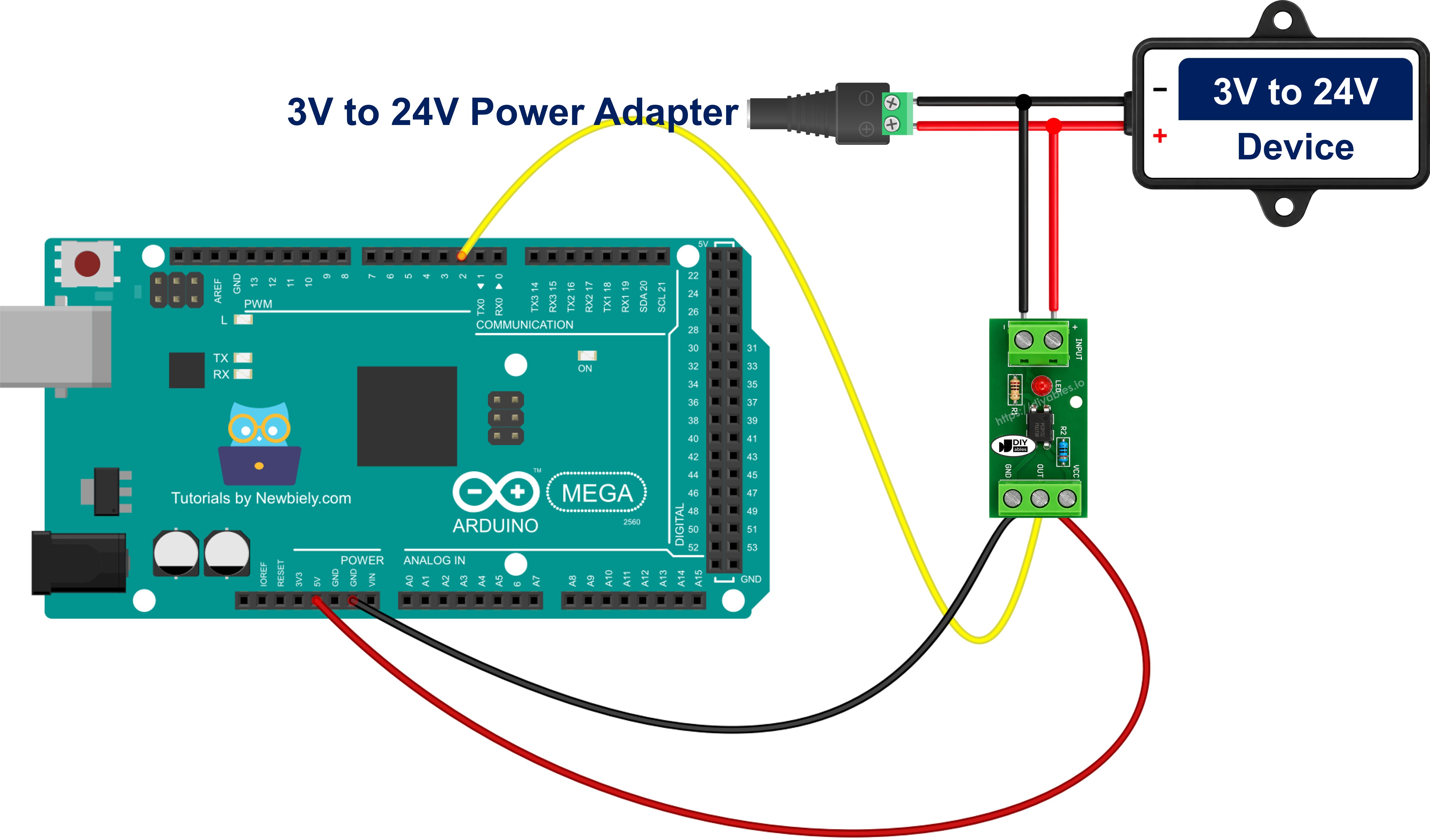
This image is created using Fritzing. Click to enlarge image
※ NOTE THAT:
The pin arrangement of ready-made PC817 isolation modules is not standardised - it varies by manufacturer. Some boards label the output header VCC / GND / OUT, others use DO or OUT1..OUT8, and a few swap the order of the screw terminals. Always read the silkscreen printed on your own module before wiring it to the Arduino Mega.
On a multi-channel module the OUT1..OUTn pins simply go to consecutive pins of the Mega's 22-53 block - 22, 23, 24 and so on - while the single VCC and GND pair feeds the whole board. Before you trust what those pins report, read the section below on which way round your module's output is: that is a per-manufacturer detail, not a per-channel one.
Tapping the Module in Parallel With the Device You Want to Monitor
The table above starts from a signal that is already sitting on a pair of terminals. On a real machine you rarely have that. What you have is a device that is either energised or not, and the job is to let the Mega know which. You do that by putting the module's input ACROSS the device - in parallel with it.
※ NOTE THAT:
Never put the module input in series with the device. In series, the whole load current of the lamp, coil or motor is forced through the optocoupler's internal LED, which is rated for 20 mA - the PC817 is destroyed the moment the device switches on. The input side is a tap that sits alongside the load, never a link in the chain that feeds it.
Take the job this board is bought for: a control panel carrying a row of 24V DC status lamps - RUN, FAULT, HEATER, PUMP - and a Mega behind the door that should log which of them are lit. You fit a 24V module with as many channels as there are lamps, and every tap is the same three connections:
| Tap Point | Connects To |
|---|---|
| The lamp's switched (+) terminal | that channel's IN+ screw terminal |
| The lamp's return (-) terminal | that same channel's IN- screw terminal |
| That channel's OUT pin | one pin of the Arduino Mega's 22-53 block |
There is no resistor in that tap. The 24V module already carries the right one for a 24V lamp, which is the whole reason the variant had to match. What you must still read literally is "that same channel": four lamps means four pairs of screw terminals and four Mega pins, and you do not join the IN- terminals of different channels together to save a wire, because each tap keeps the ground reference of the lamp it belongs to. Only the Mega side is common. Some multi-channel boards do commonize their input ground on the silkscreen - if yours does, it is only usable where every tapped lamp genuinely shares one return. Nothing in the panel is cut or rerouted either: the tap hangs across the existing lamp and draws about 10 mA, which is nothing beside what a lamp, a contactor coil or a valve already pulls, so the panel behaves exactly as it did before. The measurement is read-only.
That is also what makes the reading honest. Because the tap follows the lamp itself, it reports the real state of the device - including when the PLC energises it while nobody is watching, and including when the machine is commanded on and never comes on at all. Run-hour counters, idle-time logs and "did the pump actually start?" alerts all fall out of that.
Four details decide whether the tap works:
- Polarity. The input side is an LED and conducts in one direction only. Swap IN+ and IN- and the channel never turns on - no damage, just a line that reads idle forever. Check which terminal of the tap is positive before you wire it.
- Inductive loads need a clamp diode. A contactor coil, solenoid valve, relay or motor throws a large reverse-voltage spike when it drops out, and the PC817 input LED is rated for only 6 V in reverse. Fit an ordinary diode in reverse-parallel right across the IN+ and IN- terminals - diode cathode to IN+, diode anode to IN-. In normal operation it is reverse-biased and does nothing; on a spike it conducts and clamps the reverse voltage to well under a volt. A 1N4148 suits a small tap, a 1N4007 a heavier one.
- Leaky solid-state outputs give false readings. PLC transistor outputs, triac outputs and LED-lamp drivers often leak a little current even when they are switched off, and enough leakage lights the PC817 LED just enough to register. The symptom is unmistakable: a channel that reports LIVE and never goes back to idle. Fit a bleeder resistor of about 4.7 kohm to 10 kohm across the same IN+ / IN- terminals, so the leakage drains through it instead of through the optocoupler.
- DC only. The PC817 input is a single LED, so it answers to one polarity; it is the wrong part for sensing an AC line, which needs an optocoupler whose input stage carries two back-to-back LEDs.
One honest limitation to keep in mind: this tells you the device is energised, not that it is doing its job. A seized pump motor or a burnt-out heater element still draws power and will still read as LIVE on the Mega.
Optional: Building the Same Input From the Bare Chip
If you would rather solder the raw 4-pin DIP than buy a board, the chip gives you the same isolation without the resistor, LED or terminals. Pins 1 and 2 are the isolated side: pin 1 is the Anode, fed from the monitored line through a series resistor, and pin 2 is the Cathode, tied to the ground of that circuit and never to the Mega. Pins 3 and 4 are the Mega side: pin 3 is the Emitter, wired to Mega GND, and pin 4 is the Collector, wired to digital pin 2.
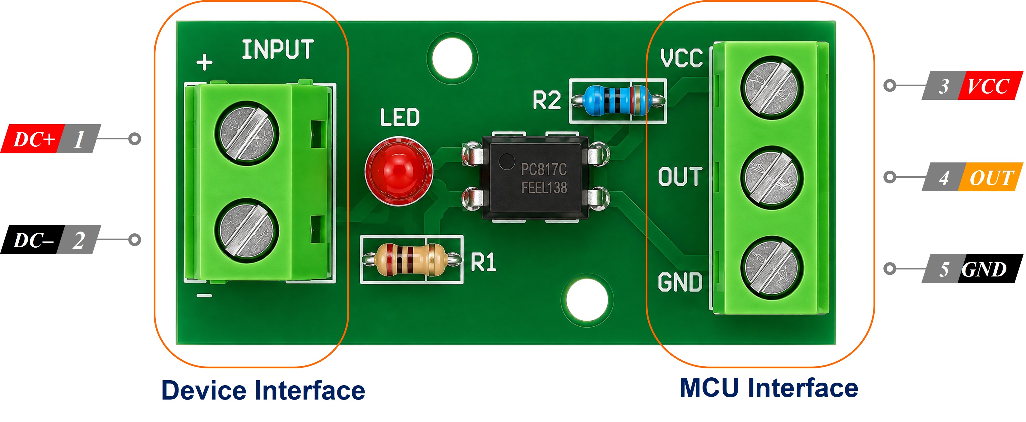
The resistor is the part the module was doing for you. Size it with R = (Vin - 1.2) / 0.01 for a 10 mA LED current: 3.3V DC needs 220 ohm, 5V DC needs 390 ohm, 12V DC needs 1 kohm, and 24V DC needs 2.2 kohm at 1/2 W. Getting that value right is the bare-chip form of the variant decision - leaving 1 kohm in place when a tap moves from 12V to 24V drives about 23 mA through a 20 mA LED.
No external pull-up resistor is needed on pin 4 - the sketch switches on the Mega's internal one.
Optocoupler Module: Active-HIGH or Active-LOW?
This is the single point that trips up most people the first time, and on a Mega you can make the mistake on thirty-two pins at once, so settle it before you write any logic.
On the bare chip the answer is fixed physics. The collector goes to a Mega digital pin held up by its internal pull-up resistor, which means:
- External 12V DC / 24V DC signal PRESENT → LED on → the transistor conducts → the Mega pin reads LOW
- External 12V DC / 24V DC signal ABSENT → LED off → the transistor is off → the Mega pin reads HIGH
So on a bare chip a live line reads LOW. On a module, that is only the common case. Some manufacturers put an inverting stage on the output side so the pin follows the input instead, and both kinds sell under the same "PC817 optocoupler isolation module" description with nothing on the listing to tell them apart. Measure yours rather than assuming.
The check takes under a minute:
- Wire one channel to pin 2 and upload the single-channel sketch below - it prints the raw pin level next to the state it derives from it.
- Leave the input screw terminals unconnected and read what the Serial Monitor prints.
- Apply the signal to the input terminals and read it again.
- Whichever raw value shows up while the signal is present is your module's active level. If it is LOW, the sketch is already correct.
- Cross-check with the module's own status LED. That LED lights when the input side is energised, so it is your ground truth: LED lit with the pin at LOW means active-LOW, LED lit with the pin at HIGH means active-HIGH.
If your board turns out to be active-HIGH you do not rewrite anything. Both sketches on this page carry one constant at the top:
Set it to false and every channel on the board follows, because the output stage is the same for all of them. Do check each board separately though - if you run a 24V module and a 3-5V module on the same Mega, they can easily disagree.
How To Program For PC817 Optocoupler
No library is needed for the PC817 optocoupler. It is plain digital input reading, and it takes three steps.
- Step 1 - set the pin as an input with the built-in pull-up resistor, so the pin sits at a defined HIGH while the external line is dead:
- Step 2 - read the raw pin level with digitalRead():
- Step 3 - turn that raw level into "the external line is live", using the polarity constant so the same sketch fits either kind of module:
Comparing signalActive with its value from the previous loop is all you need to catch the moment a 24V DC line switches on or off.
Arduino Mega Code for PC817 Optocoupler
This first sketch monitors a single isolated channel on pin 2 and prints a line only when the state of the external line changes. It reports the raw pin level alongside the state, which is what makes it usable as the polarity test described above.
Detailed Instructions
Follow these steps one by one.
- Pick the module variant that matches your input voltage - 3-5V, 12V or 24V - or size a series resistor if you are taking the bare chip route.
- Wire the PC817 isolation module to the Arduino Mega as shown in the diagram, keeping the 12V DC / 24V DC ground away from the Mega GND.
- Connect the Arduino Mega to your computer with a USB cable.
- Open the Arduino IDE on your computer.
- Choose the correct board (Arduino Mega) and the right COM port.
- Copy the code above and open it in the Arduino IDE.
- Click the Upload button in the Arduino IDE to upload the code to the Arduino Mega.
- Open the Serial Monitor.
- Switch the external 12V DC / 24V DC line on and off a few times.
- See the result in the Serial Monitor.
If your Serial Monitor shows raw=HIGH while the module's status LED is lit, you have an active-HIGH board - set MODULE_ACTIVE_LOW to false and upload again.
Arduino Mega Code to Monitor Several Devices On or Off at Once
The Mega's 54 digital pins are the reason to pick this board for the job. Past a single channel, leave pin 2 behind and move the group into the 22-53 block, where the channels sit next to each other on the double header. The sketch below watches four isolated lines on pins 22, 23, 24 and 25 - four status lamps, four contactor coils or four PLC outputs, read through one 4-channel module of the variant those lines call for (a 4-channel 24V module for a row of 24V DC lamps), or through four bare PC817 chips each with its own series resistor. The polarity constant is declared once and applied to every channel, because a module's output stage is the same on all of them.
Detailed Instructions
- Wire OUT1 to OUT4 of the 4-channel module to Arduino Mega pins 22, 23, 24 and 25.
- Wire the module VCC to 5V and the module GND to the Mega GND.
- Wire each pair of input screw terminals to one of the four lines you want to watch, all of them at the voltage this module variant is built for.
- Upload the code and open the Serial Monitor.
- Energise the lines one at a time and watch the map change.
Additional Knowledge
Why does pin count matter so much when you isolate inputs? Because isolation does not scale the way a bus does. An I2C sensor gives you a dozen readings over two wires, but every isolated line is one PC817 optocoupler and one dedicated digital pin - there is no sharing, by design, since sharing would defeat the isolation. A 24V DC control panel with eight status lines needs eight pins, full stop.
That is where the Arduino Mega separates itself from smaller boards. Pins 22 to 53 form one continuous 32-pin block along the double header, physically lined up opposite each other, so a ribbon cable from an 8-channel PC817 isolation module drops straight onto consecutive pins with no jumper spaghetti. You can run four such modules and still have pins left for a relay board and a display.
Three practical notes when you grow past one channel:
- Plan your pin blocks by voltage, because the modules force you to. A 24V module and a 12V module are different products, so a mixed panel needs one of each - decide which pins belong to which board while it is still a drawing, not after the wiring is in the trunking.
- Check the polarity of each board you add, not just the first one. Two modules bought months apart can behave differently, and that is exactly the kind of fault that looks like a wiring error for an hour.
- The PC817 switches in a few microseconds, so it does not slow anything down. What can be slow is a mechanical contact at the other end of the isolated line - a relay or a contactor coil bouncing. If your counts look inflated, apply the same software debouncing you would use for a button or a mechanical switch.
Common uses for this circuit on a Mega are watching several 24V DC PLC outputs or "running"/"fault" lamp lines on a machine panel at the same time, and sensing whether a 12V DC or 24V DC contactor or solenoid coil is actually energised - which you can then act on with a relay or log against a door sensor on the same board. Once the taps are in place, the sketch above is one step away from the things people actually want from a panel: a run-hour counter for each machine, an alert when the pump is commanded on but its lamp never lights, and an idle-time log that shows which cell on the line spends its shift waiting.