Arduino Nano 33 IoT - Button
The button is a simple part used in many Arduino Nano 33 IoT projects. It may look easy, but because of its moving parts and design, it can be tricky. Beginners might have some problems with it. This lesson is made to help beginners. Let's start!
※ NOTE THAT:
Before we talk about the button, we want to mention two common mistakes that beginners usually encounter:
1. Floating Input Issue:
- Problem: When you connect a button to an Arduino Nano 33 IoT input pin, the pin's reading is random and does not match the actual button press.
- Reason: The button is not connected with a pull-down resistor or a pull-up resistor.
- Fix: Use a pull-down or pull-up resistor on the input pin. More details will be provided later.
2. Chattering:
- Problem: The Arduino Nano 33 IoT reads the button by noticing a change from HIGH to LOW or LOW to HIGH. However, when you press the button only once, the code sometimes thinks it was pressed many times.
- Reason: Due to the button's design, one press can make the input pin quickly switch between LOW and HIGH several times.
- Fix: Use a debounce method. More information is available in the Arduino Nano 33 IoT - Button - Debounce tutorial.
Chattering only affects certain projects where you need to count the exact number of button presses; in other cases, it is not a serious problem.
Hardware Preparation
Or you can buy the following kits:
| 1 | × | DIYables Sensor Kit (18 sensors/displays) |
Additionally, some of these links are for products from our own brand, DIYables .
Overview of Button
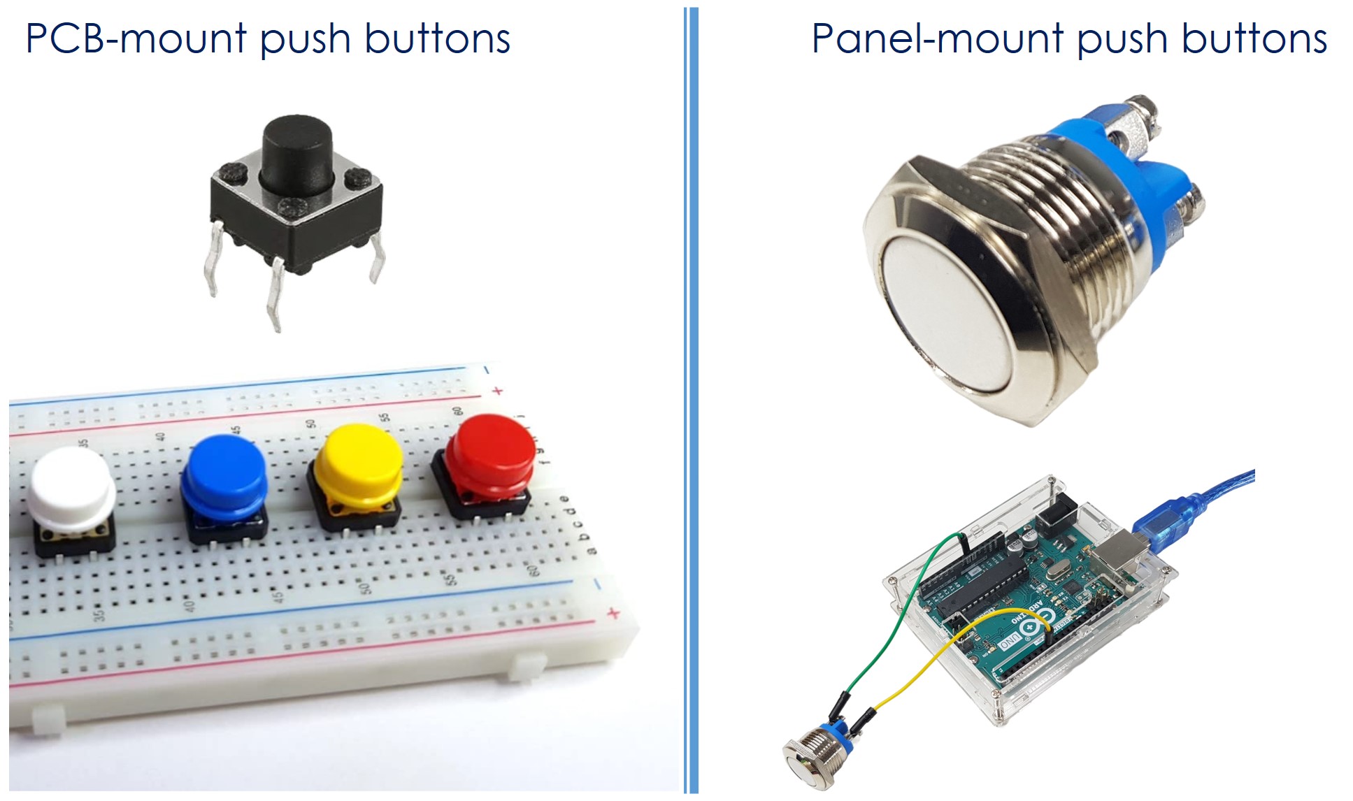
A push button, also known as a pushbutton, tactile button, or momentary switch, is a switch that closes when you press and hold it, and opens when you let go. There are many kinds of push buttons, usually divided into two groups:
- PCB-mount push buttons (suitable for breadboard mounting)
- Panel-mount push buttons
Button Pinout
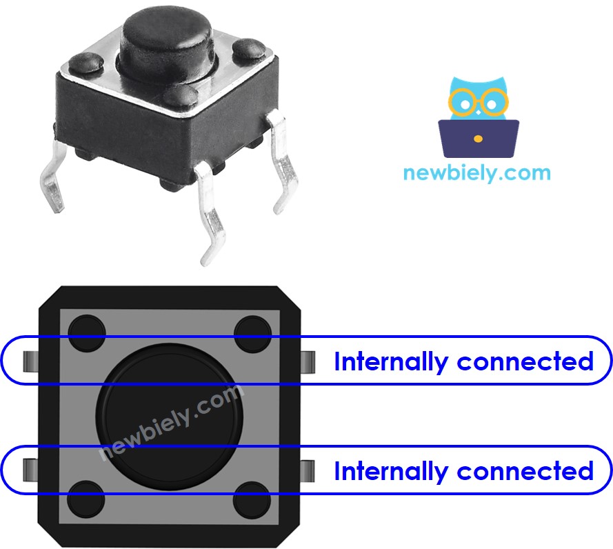
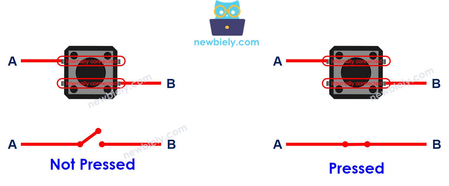
A PCB-mount button usually has four pins that are internally connected in pairs.
We only need two of the four pins, and they should not be directly connected. So, there are four different ways to connect the button (see the image below).
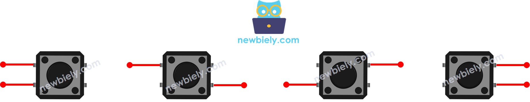
Due to symmetry, the four options reduce to two. In the rest of this guide, we will use two pins: Pin A and Pin B, which are not connected to each other.
Why does the button have four pins when we only need two?
The button is pressed by users. To keep it secure on the printed circuit board (PCB), it uses four pins to hold it in place when pressed.
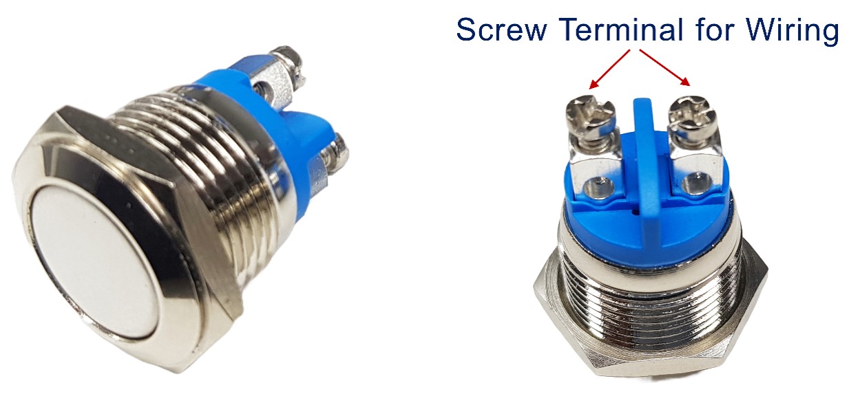
A panel-mount button usually has two pins.
The push button module includes an built-in pull-down resistor, which ensures that the output remains LOW when the button is not pressed. It has three pins:
- GND: Attach this pin to the ground.
- VCC: Connect this pin to a 3.3V power source.
- OUT: Connect this pin to a digital input on your Arduino Nano 33 IoT.
In this setup, the device gives a LOW signal when the button is not pressed and a HIGH signal when it is pressed.
How Button Works
- When you press the button, pin A connects to pin B.
- When you do not press the button, pin A does not connect to pin B.
Arduino Nano 33 IoT - Button
One button lead is connected to a digital input on the Arduino Nano 33 IoT. The other lead is connected to either VCC or GND. In the Arduino code, by checking the digital input, we can tell if the button is pressed or not.
Input State and Pressing State
The connection between the input pin's condition and whether the button is pressed depends on how you hook up the button to the Arduino Nano 33 IoT and how you set up the Arduino's pin. There are two ways to use a button with the Arduino Nano 33 IoT:
- Method 1:
- Connect one side of the button to a digital input pin on the Arduino Nano 33 IoT and the other side to VCC (power).
- You must use a pull-down resistor.
- When the button is pressed, the pin reads as HIGH (active). When the button is not pressed, the pin reads as LOW (inactive).
- Method 2:
- Connect one side of the button to a digital input pin on the Arduino Nano 33 IoT and the other side to GND (ground).
- You must use a pull-up resistor.
- When the button is pressed, the pin reads as LOW (active). When the button is not pressed, the pin reads as HIGH (inactive).
※ NOTE THAT:
If you don't use a pull-down or pull-up resistor, the input pin can randomly be HIGH or LOW when the button is not pressed. This is called the floating input problem and may cause the system to work incorrectly.
This guide is easy for beginners. We suggest using the built-in pull-up resistor on the Arduino Nano 33 IoT pin. You don't need any extra resistor. This saves hardware and makes the wiring diagram simpler.
Wiring Diagram between Button and Arduino Nano 33 IoT
- Wiring diagram for connecting the Arduino Nano 33 IoT to a PCB-mounted button.
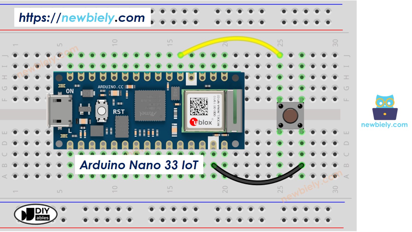
This image is created using Fritzing. Click to enlarge image
- Wiring Diagram for Connecting the Arduino Nano 33 IoT to a Panel Button
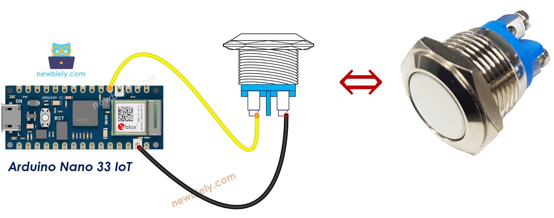
This image is created using Fritzing. Click to enlarge image
※ NOTE THAT:
Please note that the Arduino Nano 33 IoT pins A4 and A5 have built-in pull-up resistors for I2C communication. Although these pins can be used as digital input pins, it is recommended to avoid using them for digital input. If you must use them, do NOT use internal or external pull-down resistors for these pins
Arduino Nano 33 IoT Code
Detailed Instructions
If you are new to the Arduino Nano 33 IoT, be sure to check out our Getting Started with Arduino Nano 33 IoT tutorial. Then, follow these steps:
- Connect the components to the Arduino Nano 33 IoT board as depicted in the diagram.
- Use a USB cable to connect the Arduino Nano 33 IoT board to your computer.
- Launch the Arduino IDE on your computer.
- Select the Arduino Nano 33 IoT board and choose its corresponding COM port.
- Copy the following code and paste it into the Arduino IDE.
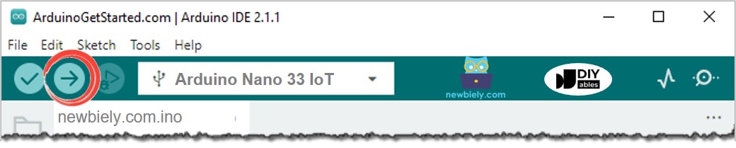
- Click the Upload button in the Arduino IDE to build your program and send it to your Arduino Nano 33 IoT board.
- Open the Serial Monitor in the Arduino software.
- Press and let go of the button several times.
- Look at the output on the Serial Monitor. It should look like what is shown below.
1 means high, and 0 means low.
Line-by-line Code Explanation
The Arduino Nano 33 IoT code above shows an explanation for each line. Please look at the comments in the code!
Modifying Arduino Nano 33 IoT Code
Let's change the code so it can see when something is pressed and let go.
Detailed Instructions
- Change the code as shown below.
- Click the Upload button on the Arduino IDE to compile and send the code to the Arduino Nano 33 IoT board.
- Open the Serial Monitor in the Arduino IDE.
- Press and then release the button.
- Look at the result on the Serial Monitor. It should look like the image below.
※ NOTE THAT:
The Serial Monitor might show several press and release messages even if you only pressed and released the button once. This is normal and is known as the chattering phenomenon. In some projects, you need a way to remove this extra information. You can find out more in the Arduino Nano 33 IoT - Button Debounce tutorial.
To keep things simple for beginners, especially when using several buttons, we made a library called ezButton. You can learn more about it here: https://arduinogetstarted.com/tutorials/arduino-button-library.
When using the button module, set the pin as an input by using pinMode(BUTTON_PIN, INPUT). The module gives a LOW signal when not pressed and a HIGH signal when pressed.
Video Tutorial
Additional Knowledge
When should I use a pull-down or pull-up resistor, and when should I not?
- SHOULD: When a sensor has two conditions—closed or open—you need to add a pull-up or pull-down resistor. This resistor helps change the conditions into two clear levels: LOW and HIGH. Examples include push-buttons, switches, and magnetic door sensors.
- SHOULD NOT: When the sensor already gives two clear voltage levels (LOW and HIGH), you do not need a pull-up or pull-down resistor. Examples include motion sensors and touch sensors.