Arduino Nano 33 IoT - TM1637 4-Digit 7-Segment Display
Discover how to use a TM1637 4-digit 7-segment display with the Arduino Nano 33 IoT. The Nano 33 IoT runs a SAMD21 Cortex-M0+ processor at 48 MHz, includes built-in Wi-Fi and Bluetooth Low Energy, and operates at 3.3V logic. Despite all that, it keeps the same compact Nano footprint. The TM1637 module works at both 3.3V and 5V, so it connects directly without level shifting.
Along the way, you will discover:
- How to wire the TM1637 display to the Arduino Nano 33 IoT.
- How to show integers, text, and temperature on the display.
- How to display time in HH:MM format with a blinking colon.
- How to control each digit individually and adjust brightness.
Hardware Preparation
Or you can buy the following kits:
| 1 | × | DIYables Sensor Kit (18 sensors/displays) |
Additionally, some of these links are for products from our own brand, DIYables .
Introducing the TM1637 Display Module
The TM1637 is a controller IC purpose-built for driving 7-segment LED displays. It manages all the LED multiplexing internally and stores the display data in its own registers. Once you send a value to the chip, the display holds it without any refresh loop from your code. Communication happens through a lightweight 2-wire protocol using CLK and DIO lines.
What makes this module useful:
- 4 digits with 7 segments and a decimal point each
- Colon LED between digit 1 and digit 2 for clock-style readouts
- 8 brightness levels adjustable through software
- 2-wire serial interface, compatible with 3.3V and 5V
- Persistent display - no continuous updates needed
| Function | Pin |
|---|---|
| CLK | Clock signal input |
| DIO | Data input/output |
| VCC | Power supply (3.3V or 5V) |
| GND | Ground |
Any two digital pins on the Nano 33 IoT can serve as CLK and DIO. The examples use pins 2 and 3.
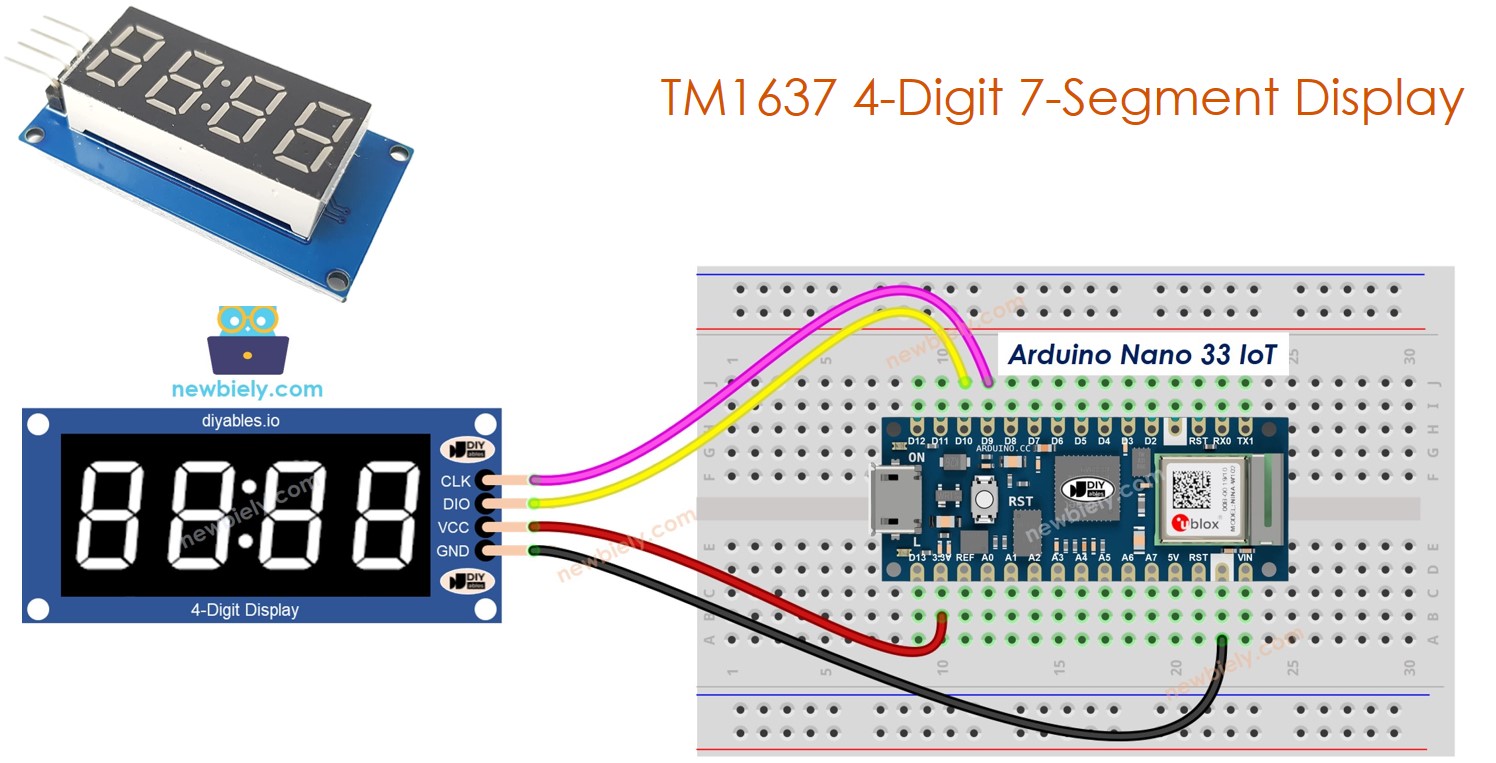
Wiring Diagram
Connect the TM1637 module to the Arduino Nano 33 IoT:
- CLK to pin 9
- DIO to pin 10
- VCC to 3.3V
- GND to GND
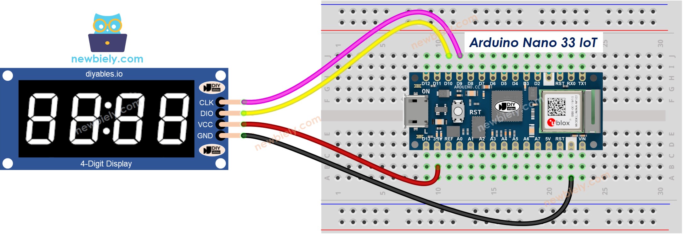
This image is created using Fritzing. Click to enlarge image
Preparing the Library
- Connect the Arduino Nano 33 IoT to your computer using a Micro-B USB cable.
- In Arduino IDE, choose Arduino NANO 33 IoT as the board and select the correct port.
- Open the Libraries panel from the left sidebar.
- Search for "DIYables_4Digit7Segment_TM1637" and locate the one published by DIYables.
- Press Install to add it.
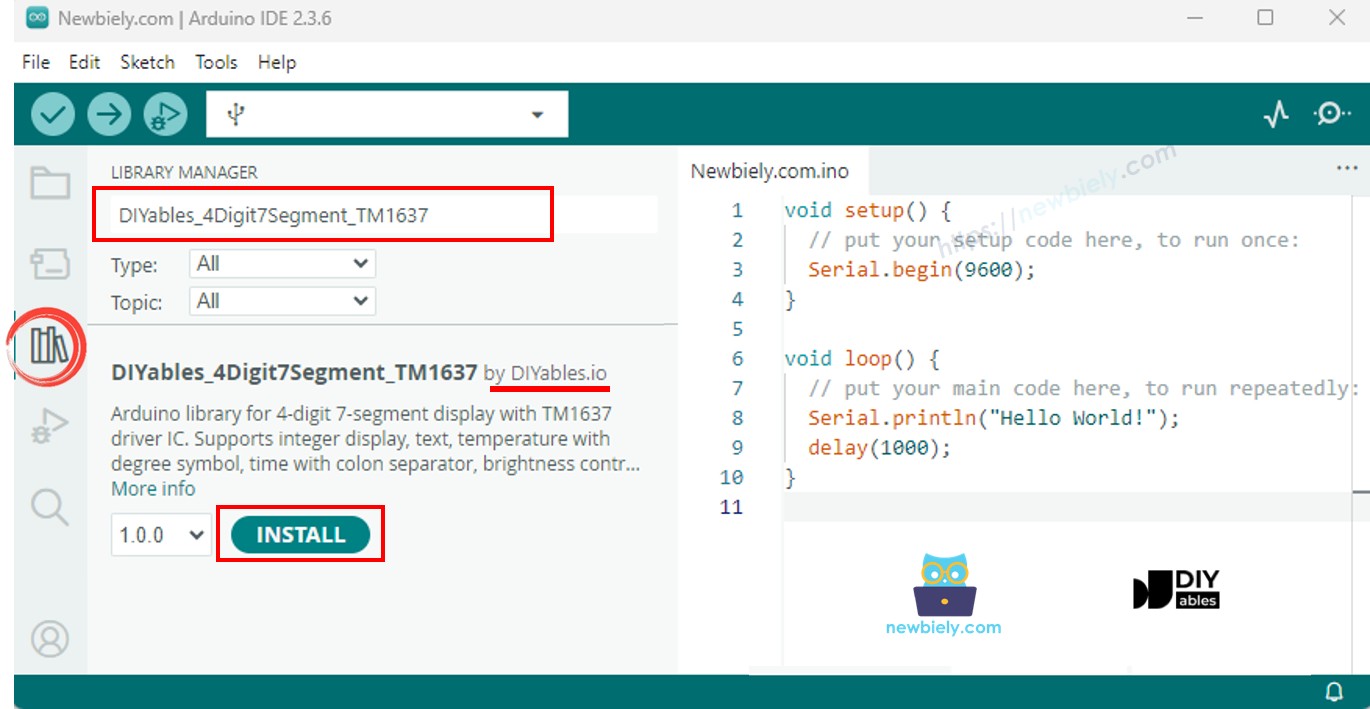
No additional dependencies needed - everything is bundled in.
Note: If the board does not appear in the board list, install the Arduino SAMD Boards core via the Boards Manager.
Core Sketch
The core structure that every DIYables_4Digit7Segment_TM1637 sketch builds on:
Pass the pin numbers to the constructor, call begin(), and you are ready to send data to the display.
Discover - Display Integer Numbers
Explore how the display handles various integer values including negatives and zero-padded output.
Give It a Try
- Connect the TM1637 module to the Nano 33 IoT as shown in the wiring diagram.
- Connect the board to your computer with a Micro-B USB cable.
- In Arduino IDE, select the board and port, paste the code, and press Upload.
- Open the Serial Monitor to see what happens.
The display cycles through 0, 42, 1234, -5, -123, 9999, and then shows "0042" with zero-padding.
API Essentials
| Method | Role | Usage Example |
|---|---|---|
| print(int) | Display an integer (-999 to 9999) | display.print(1234) |
| print(int, true) | Display with leading zeros | display.print(42, true) |
| clear() | Clear the display | display.clear() |
Discover - Display Text and Temperature
Explore how the display renders text strings and temperature values with the degree symbol.
Give It a Try
- Wire the module as shown above.
- Upload the sketch and open the Serial Monitor.
The display shows "HELP", "Hi", "COOL", "done", then temperatures "25°C" and "72°F".
API Essentials
| Method | Role | Usage Example |
|---|---|---|
| print(const char*) | Display a text string (up to 4 chars) | display.print("HELP") |
| printTemperature(int, char) | Display temperature with degree and unit | display.printTemperature(25, 'C') |
| DEGREE | Degree symbol constant | display.DEGREE |
Discover - Display Time with Blinking Colon
Explore clock-style time display with the colon toggling every half second.
Give It a Try
- Upload and observe "12:30" with the colon blinking on and off.
API Essentials
| Method | Role | Usage Example | |
|---|---|---|---|
| printTime(int, int) | Display time HH | MM with colon | display.printTime(12, 30) |
| printTime(int, int, bool) | Display time, control colon on/off | display.printTime(12, 30, false) |
Discover - Blink the Display
Explore how off() and on() create a blinking effect while the display data is preserved.
Give It a Try
- Upload and watch "1234" blink five times, then "HELP" blink five times.
API Essentials
| Method | Role | Usage Example |
|---|---|---|
| off() | Turn display off, data stays | display.off() |
| on() | Turn display back on | display.on() |
| setBrightness(int) | Set brightness 0-7 | display.setBrightness(4) |
Discover - Individual Digit Control
Explore setting each digit position independently with numbers, characters, and the colon.
Give It a Try
- Upload and see the display cycle through different digit and character combinations.
API Essentials
| Method | Role | Usage Example |
|---|---|---|
| setNumber(int, int) | Set a digit (0-9) at position 0-3 | display.setNumber(0, 1) |
| setChar(int, char) | Set a character at position 0-3 | display.setChar(0, 'H') |
| setColon(bool) | Turn colon on or off | display.setColon(true) |
| setSegments(int, uint8_t) | Set raw segments at position 0-3 | display.setSegments(0, 0x76) |
Troubleshoot
- Display is blank -- Check wiring. Verify CLK and DIO are connected to the right pins and VCC goes to 3.3V.
- Wrong characters on the display -- CLK and DIO may be swapped. Try switching the two wires.
- Display too dim -- Call setBrightness(7) for maximum brightness.
- Library not found during compile -- Install DIYables_4Digit7Segment_TM1637 from the Library Manager.
- Board not recognized -- Make sure you have the Arduino SAMD Boards core installed via the Boards Manager.
Platform Support
Built on Arduino standard APIs - runs on every Arduino-compatible platform (architectures=*).