Arduino Nano 33 IoT - RS422
This guide shows you how to use RS422 communication with your Arduino Nano 33 IoT. We will learn by following these steps:
- How to hook up the Arduino Nano 33 IoT with the TTL to RS422 module.
- How to write a program for the Arduino Nano 33 IoT to get data from the TTL to RS422 module.
- How to write a program for the Arduino Nano 33 IoT to send data to the TTL to RS422 module.
- How to transfer data both ways between your computer and the Arduino Nano 33 IoT using RS422.
Hardware Preparation
Or you can buy the following kits:
| 1 | × | DIYables Sensor Kit (18 sensors/displays) |
Additionally, some of these links are for products from our own brand, DIYables .
Overview of TTL to RS422 Module
When you use serial communication on the Arduino Nano 33 IoT with commands like Serial.print(), Serial.read(), and Serial.write(), data is sent from the TX pin and received by the RX pin. These pins work at TTL level, which means they handle signals that only travel a short distance. So, if you want to send data over longer distances, you need to change the TTL signal to RS232, RS422, or RS485 standards.
This guide shows how to work with RS422 on the Arduino Nano 33 IoT. We use a TTL to RS422 module that changes TTL signals into RS422 signals and back.
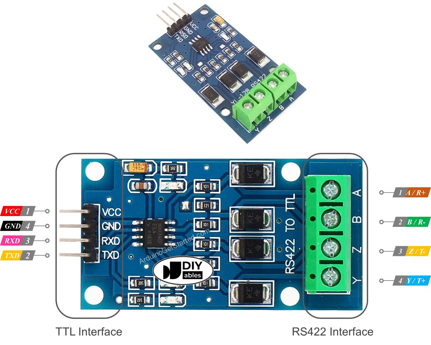
Pinout
The RS422 to TTL module comes with two ports:
- TTL Interface (connected to Arduino Nano 33 IoT):
- VCC Pin: Connect this power pin to VCC (5V or 3.3V).
- GND Pin: Connect this power pin to GND (0V).
- RXD Pin: Connect this data pin to a TX pin on the Arduino Nano 33 IoT.
- TXD Pin: Connect this data pin to an RX pin on the Arduino Nano 33 IoT.
- RS422 Interface:
- A (R+) Pin: This is the RX+ pin on the module. Connect it to the TX+ pin (or T+ / Y pin) on the other RS422 device.
- B (R-) Pin: This is the RX- pin on the module. Connect it to the TX- pin (or T- / Z pin) on the other RS422 device.
- Y (T+) Pin: This is the TX+ pin on the module. Connect it to the RX+ pin (or R+ / A pin) on the other RS422 device.
- Z (T-) Pin: This is the TX- pin on the module. Connect it to the RX- pin (or R- / B pin) on the other RS422 device.
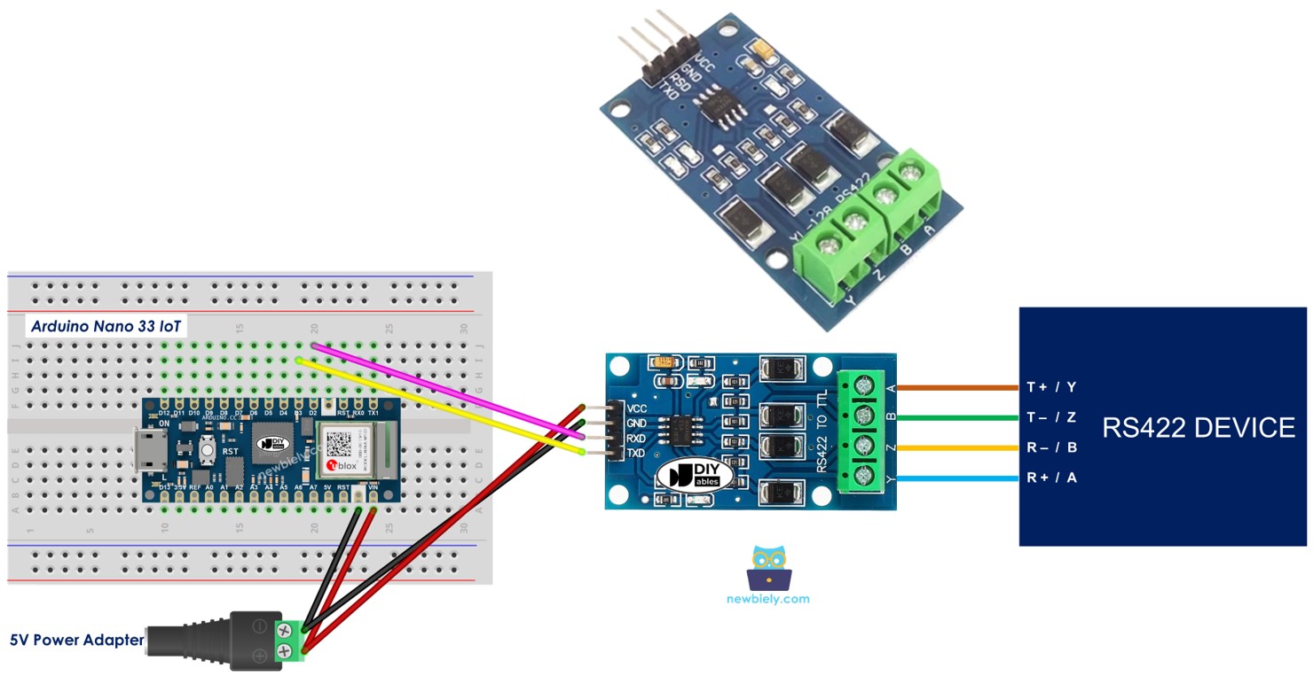
Wiring Diagram
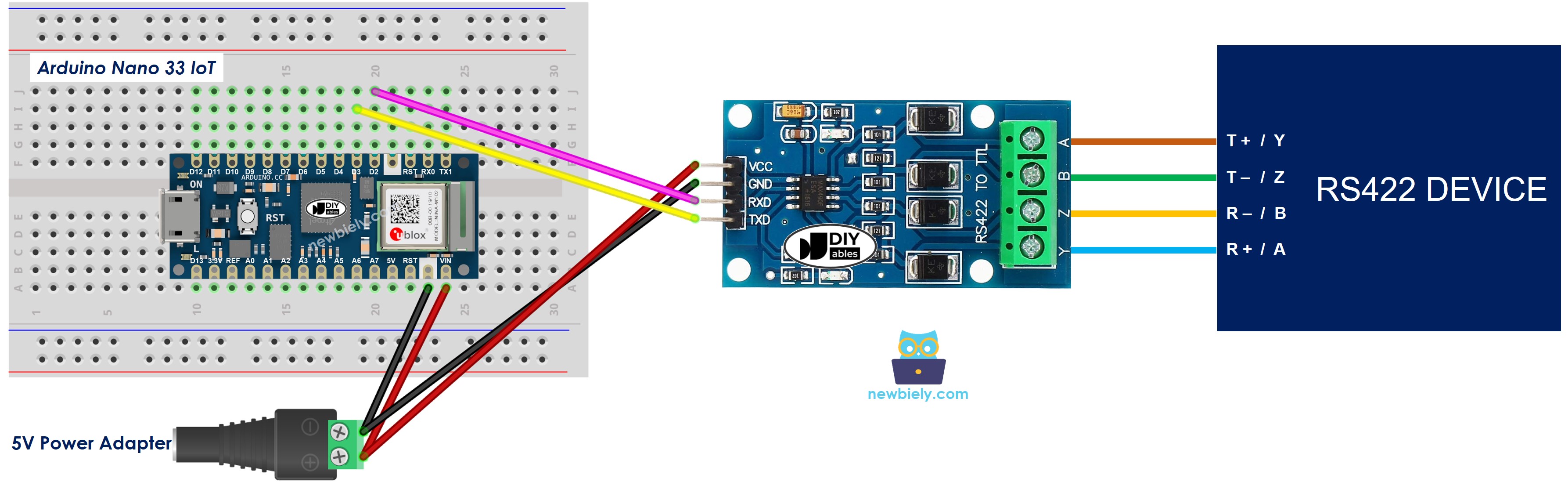
This image is created using Fritzing. Click to enlarge image
How To Program Arduino Nano 33 IoT to use the RS422 module
- Set the pins for serial communication.
- Starts the serial connection:
- To read data from RS422, you can use these functions:
- Serial.read() – reads one character.
- Serial.readBytes() – reads multiple characters.
- Serial.readBytesUntil() – reads multiple characters until a specific character is found.
- Serial.readString() – reads data as a text string.
- Serial.readStringUntil() – reads a text string until a specific character is found.
- To write data to RS422, you can use these functions:
- Serial.print() – sends data to the output.
- Serial.println() – sends data and moves to a new line.
- Serial.write() – sends raw binary data.
- You can find more RS422 functions in the Serial reference.
Arduino Nano 33 IoT Code
Testing
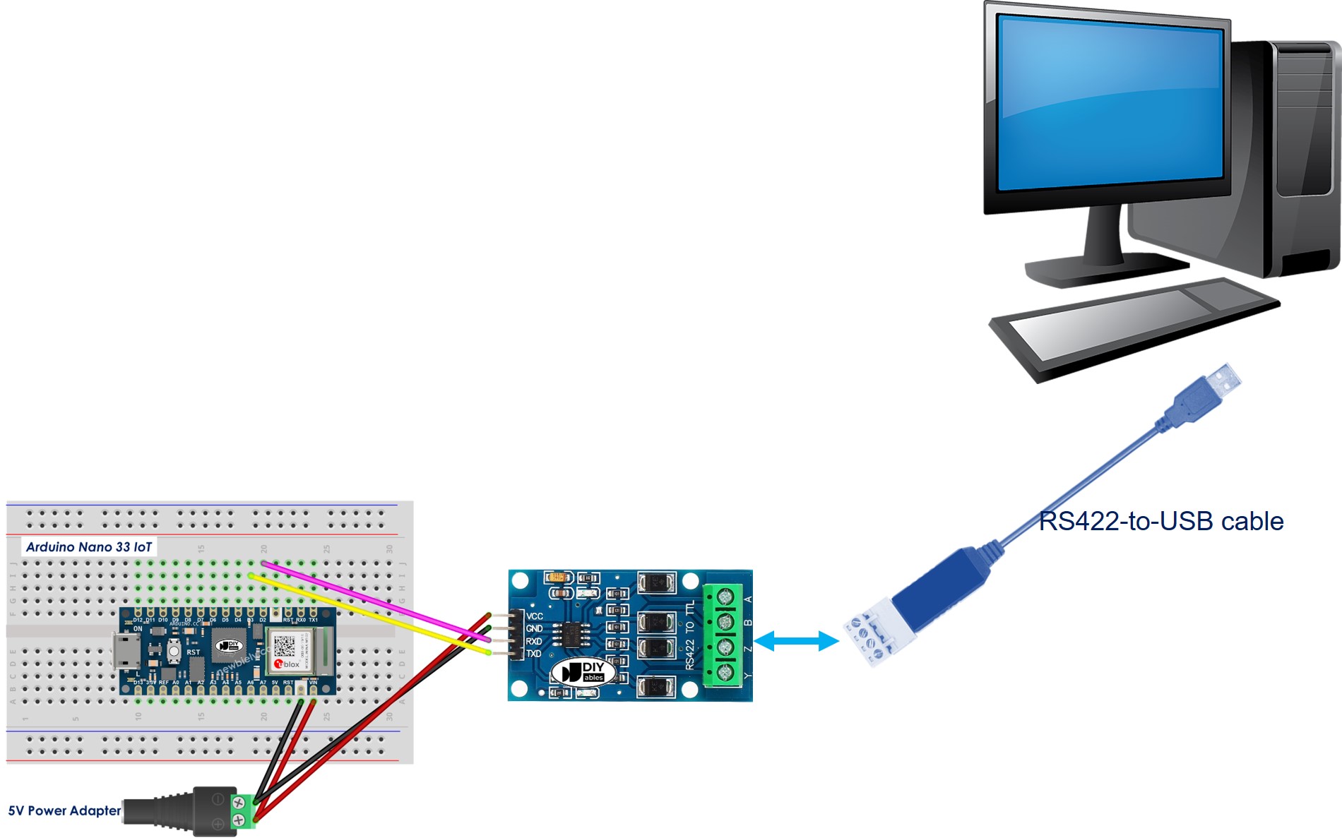
You can try a test by sending data from your computer to the Arduino Nano 33 IoT using RS-422 and then sending it back. To do this, follow these steps:
- Connect the Arduino Nano 33 IoT to your computer using an RS422-to-USB cable like the one shown below.
- Install a serial terminal program like Tera Term or PuTTY.
- Open the program and set up the serial settings (like COM port and baud rate).
- Type some text in the terminal to send it to the Arduino Nano 33 IoT.
- If it works, you'll see the text appear back in the terminal.