Arduino Nano 33 IoT - Traffic Light
In this lesson, we will learn how to use the Arduino Nano 33 IoT board to control a traffic light kit. Specifically, we will cover:
- How to hook up the traffic light module to the Arduino Nano 33 IoT
- How to write code for the Arduino Nano 33 IoT to control the RGB traffic light module
- How to write code for the Arduino Nano 33 IoT to control the RGB traffic light module without using the delay() function
Hardware Preparation
Or you can buy the following kits:
| 1 | × | DIYables Sensor Kit (18 sensors/displays) |
Additionally, some of these links are for products from our own brand, DIYables .
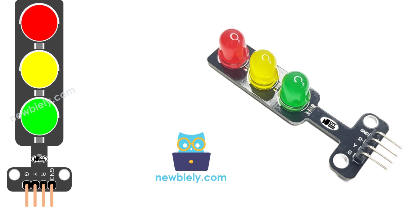
Overview of Traffic Light Module
Pinout
A traffic light module has 4 pins.
- GND pin: This is the ground. Connect it to the ground (GND) on your Arduino Nano 33 IoT.
- R pin: This pin controls the red light. Connect it to a digital output on your Arduino Nano 33 IoT.
- Y pin: This pin controls the yellow light. Connect it to a digital output on your Arduino Nano 33 IoT.
- G pin: This pin controls the green light. Connect it to a digital output on your Arduino Nano 33 IoT.
How It Works
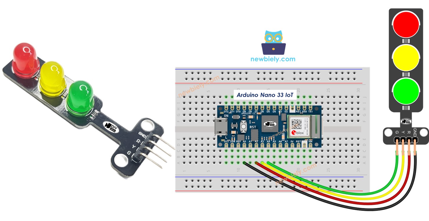
Wiring Diagram

This image is created using Fritzing. Click to enlarge image
How To Program For Traffic Light module
- Set up the pins on the Arduino Nano 33 IoT board as digital outputs using the [pinMode()] function.
- Program to switch on the red light using the digitalWrite() function.
Arduino Nano 33 IoT Code
Detailed Instructions
If you are new to the Arduino Nano 33 IoT, be sure to check out our Getting Started with Arduino Nano 33 IoT tutorial. Then, follow these steps:
- Connect the components to the Arduino Nano 33 IoT board as depicted in the diagram.
- Use a USB cable to connect the Arduino Nano 33 IoT board to your computer.
- Launch the Arduino IDE on your computer.
- Select the Arduino Nano 33 IoT board and choose its corresponding COM port.
- Copy the code above and open it in the Arduino IDE.
- Click the Upload button in the Arduino IDE to send the code to your Arduino Nano 33 IoT.
- Look at the traffic light module.
Remember that traffic lights may work differently depending on their design and the technology used in different areas and road intersections. The ideas above give a basic understanding of how traffic lights control traffic and help keep roads safe.
The code above shows how to control each light one at a time. Now, let's improve the code so it works better.
Arduino Nano 33 IoT Code Optimization
- Let's make the code better by adding a function to control the lights.
- Let's make our code better by using a for loop.
- Let's make our code better by using the millis() function rather than delay().