Arduino Nano 33 IoT - LDR Module
The LDR light sensor module can detect light and see how bright it is. It has two types of outputs: one digital output that shows either LOW or HIGH, and one analog output.
In this lesson, we will learn how to use an Arduino Nano 33 IoT and an LDR light sensor module together to find and measure light. Here is what we will talk about:
- Learn how to hook up an LDR light sensor to an Arduino Nano 33 IoT.
- Learn how to write a program for the Arduino Nano 33 IoT to detect light using the sensor's digital signal.
- Learn how to write a program for the Arduino Nano 33 IoT to check brightness using the sensor's analog signal.
Later, you can change the code to make an LED or a light bulb turn on using a relay when it detects light.
If you want to learn about a simple light sensor, check out the Arduino Nano 33 IoT - Light Sensor tutorial.
Hardware Preparation
Or you can buy the following kits:
| 1 | × | DIYables Sensor Kit (18 sensors/displays) |
Additionally, some of these links are for products from our own brand, DIYables .
Overview of LDR Light Sensor Module
The LDR light sensor module helps you check if there is light or how bright it is around it. It has one pin for digital signals and one for analog signals, giving you different ways to use it.
Pinout
The LDR light sensor has four connection points.
- VCC pin: Attach this pin to a power source that provides between 3.3V and 5V.
- GND pin: Attach this pin to the ground (0V).
- DO pin: This is a digital output pin. It sends a HIGH signal when it's dark and a LOW signal when it's light. There is a built-in knob that lets you change the level that determines dark or light.
- AO pin: This is an analog output pin. Its value goes down when the light is stronger and goes up when the light is weaker.
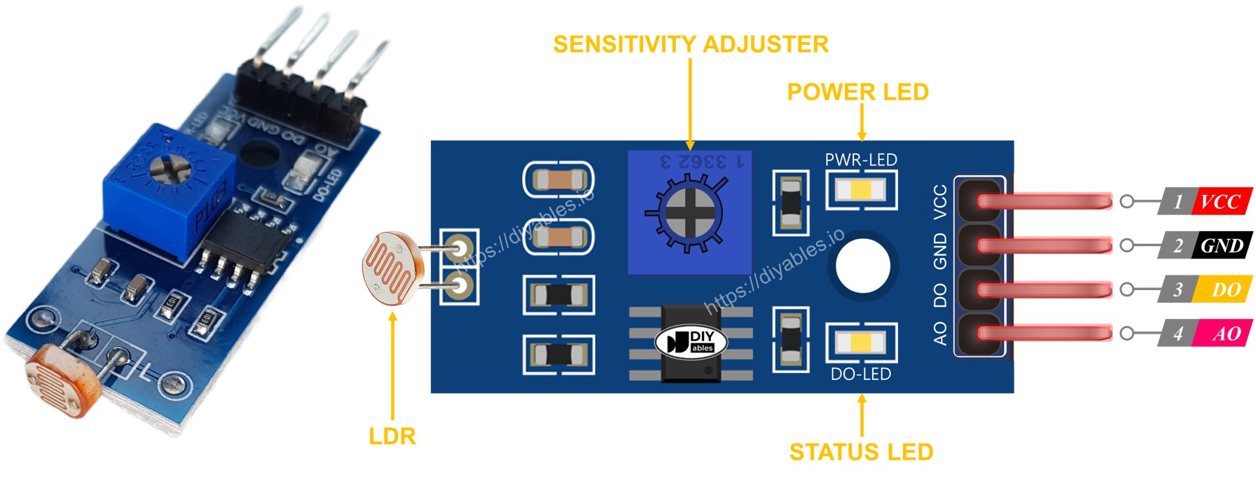
Also, the LDR light sensor module has two LED indicator lights.
- The PWR-LED light shows if the device is on.
- The DO-LED light shows the light level on the DO pin: it turns on when there’s light and stays off when it’s dark.
How It Works
About the DO pin:
- The LDR sensor module has a dial that lets you change its light sensitivity. When there is enough light (above your set level), the sensor output goes low and the DO-LED turns on. When there isn’t enough light (below your set level), the sensor output goes high and the DO-LED turns off.
About the AO pin:
- The number measured from the AO pin goes in the opposite direction of the brightness around it. In other words, if there is more light (it's brighter), the AO pin number gets smaller. On the other hand, if there is less light (it's darker), the AO pin number becomes larger.
Remember that turning the potentiometer doesn't change the number on the AO pin.
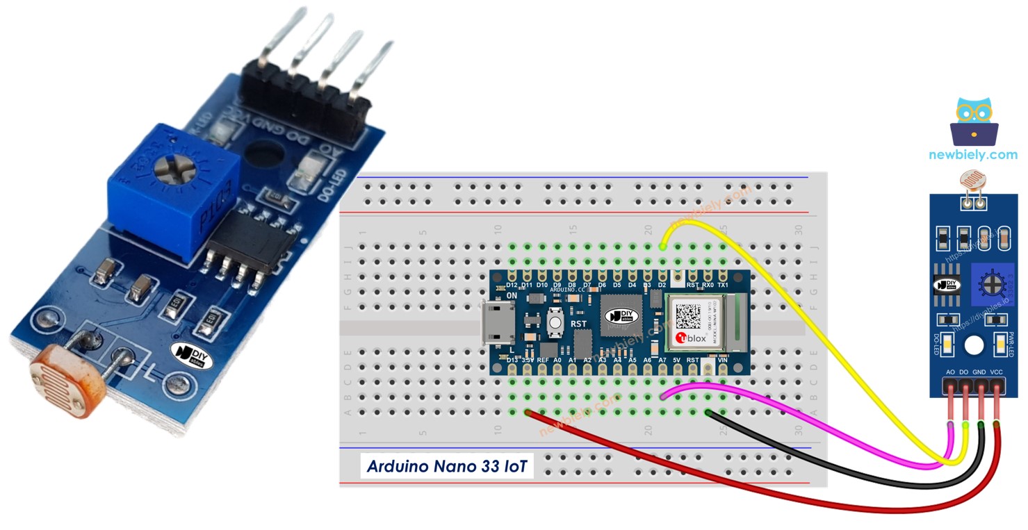
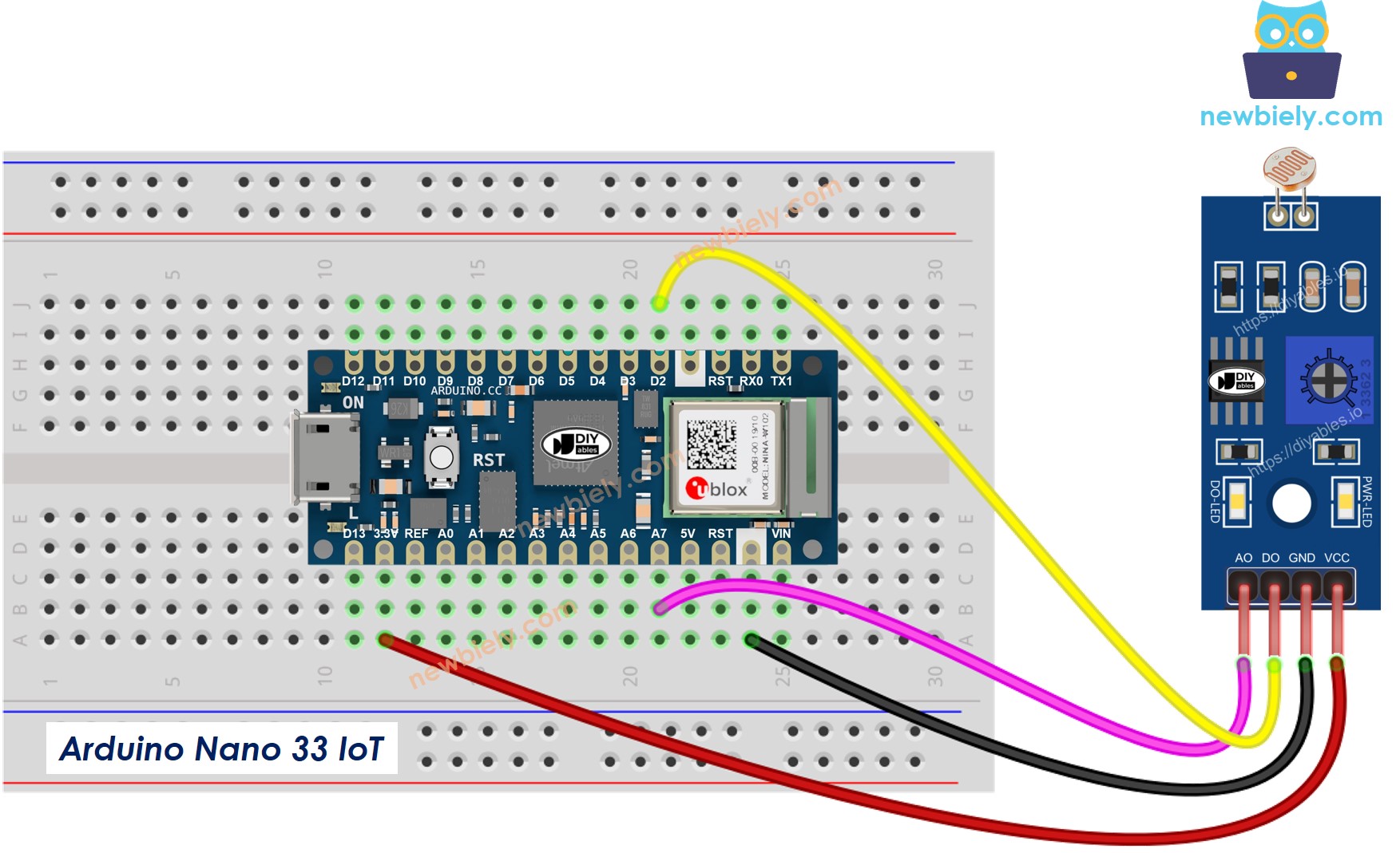
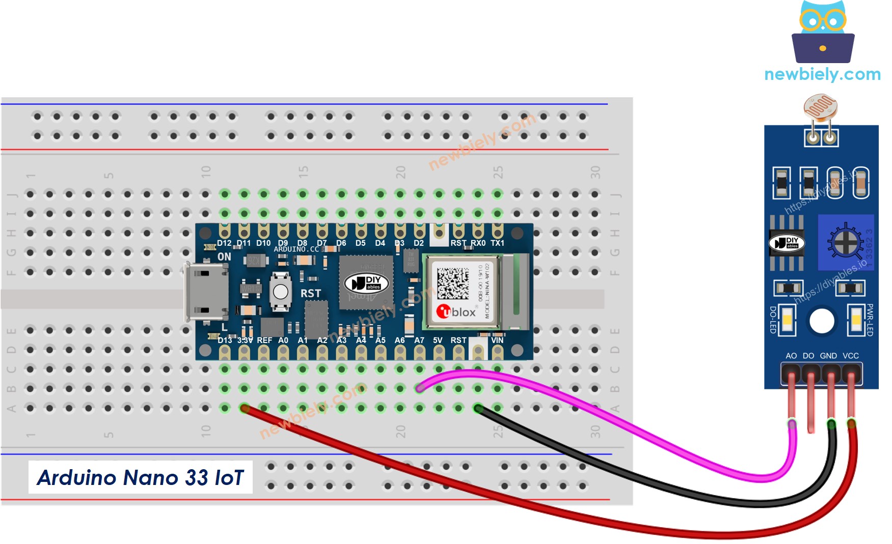
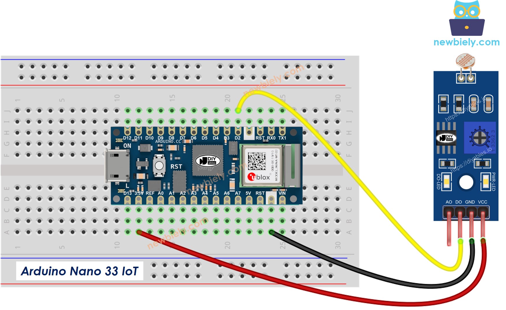
Wiring Diagram
The light sensor module has two outputs. You can choose to use one or both, depending on what you need.
- Wiring diagram connecting the Arduino Nano 33 IoT to the LDR light sensor module using both its analog and digital outputs.
This image is created using Fritzing. Click to enlarge image
- Wiring diagram that shows how to connect the Arduino Nano 33 IoT to the LDR light sensor module using only the AO pin.
This image is created using Fritzing. Click to enlarge image
- Wiring layout showing how to connect the Arduino Nano 33 IoT board to the LDR light sensor module using only the DO pin.
This image is created using Fritzing. Click to enlarge image
※ NOTE THAT:
Please note that the Arduino Nano 33 IoT pins A4 and A5 have built-in pull-up resistors for I2C communication:
- This can affect analog readings, so it is recommended to avoid using these pins with any devices/sensors that relies on ADC.
- Although these pins can be used as digital input pins, it is recommended to avoid using them for digital input. If you must use them, do NOT use internal or external pull-down resistors for these pins.
Arduino Nano 33 IoT Code - Read value from DO pin
Detailed Instructions
If you are new to the Arduino Nano 33 IoT, be sure to check out our Getting Started with Arduino Nano 33 IoT tutorial. Then, follow these steps:
- Connect the components to the Arduino Nano 33 IoT board as depicted in the diagram.
- Use a USB cable to connect the Arduino Nano 33 IoT board to your computer.
- Launch the Arduino IDE on your computer.
- Select the Arduino Nano 33 IoT board and choose its corresponding COM port.
- Copy the code above and open it using the Arduino IDE.
- Press the Upload button in the Arduino IDE to send the code to your Arduino Nano 33 IoT.
- Cover and uncover the LDR light sensor using your hand or any object.
- Look at the result in the Serial Monitor.
If you notice that the LED is always on or always off, no matter if there is light or not, you can adjust the potentiometer. This change lets you control how sensitive the sensor is to light.
You can change the code to fit your needs. For example, you can set the LED to light up when it senses light. You can also make the servo motor move. Step-by-step instructions and easy tutorials for these changes are at the end of this guide.
Arduino Nano 33 IoT Code - Read value from AO pin
Detailed Instructions
- Copy the code above and paste it into Arduino IDE.
- Click the Upload button on Arduino IDE to send the code to your Arduino Nano 33 IoT.
- Use your hand (or another object) to cover and then uncover the LDR light sensor.
- Watch the result in the Serial Monitor.