Arduino Nano 33 IoT - DC Motor
This guide explains how to use the Arduino Nano 33 IoT to control a DC motor with the L298N Motor Driver. We will show you how to set the speed and direction of the DC motor. First, you will learn to control one DC motor, and then you will learn how to control two DC motors with one L298N Motor Driver.
Hardware Preparation
Or you can buy the following kits:
| 1 | × | DIYables Sensor Kit (18 sensors/displays) |
Additionally, some of these links are for products from our own brand, DIYables .
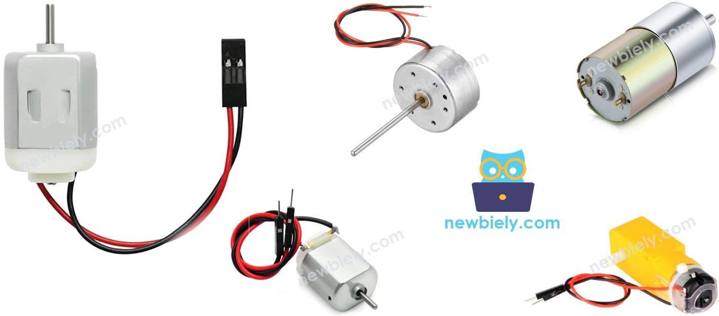
Overview of DC Motor
DC Motor Pinout
A DC Motor has two wires: one is negative (black) and the other is positive (red).
How DC Motor Works
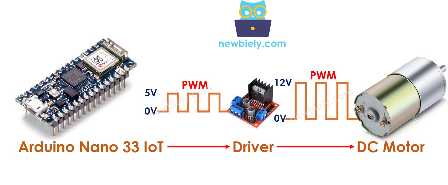
The speed and direction of a DC motor depend on how we supply power to it. The pictures below show in detail how power affects both speed and direction.
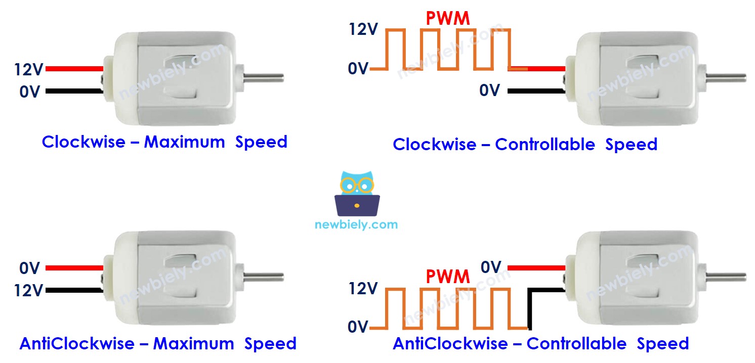
When using PWM, a higher duty cycle means the motor spins faster.
The following animation shows how a PWM signal is used to control the speed of a DC motor:
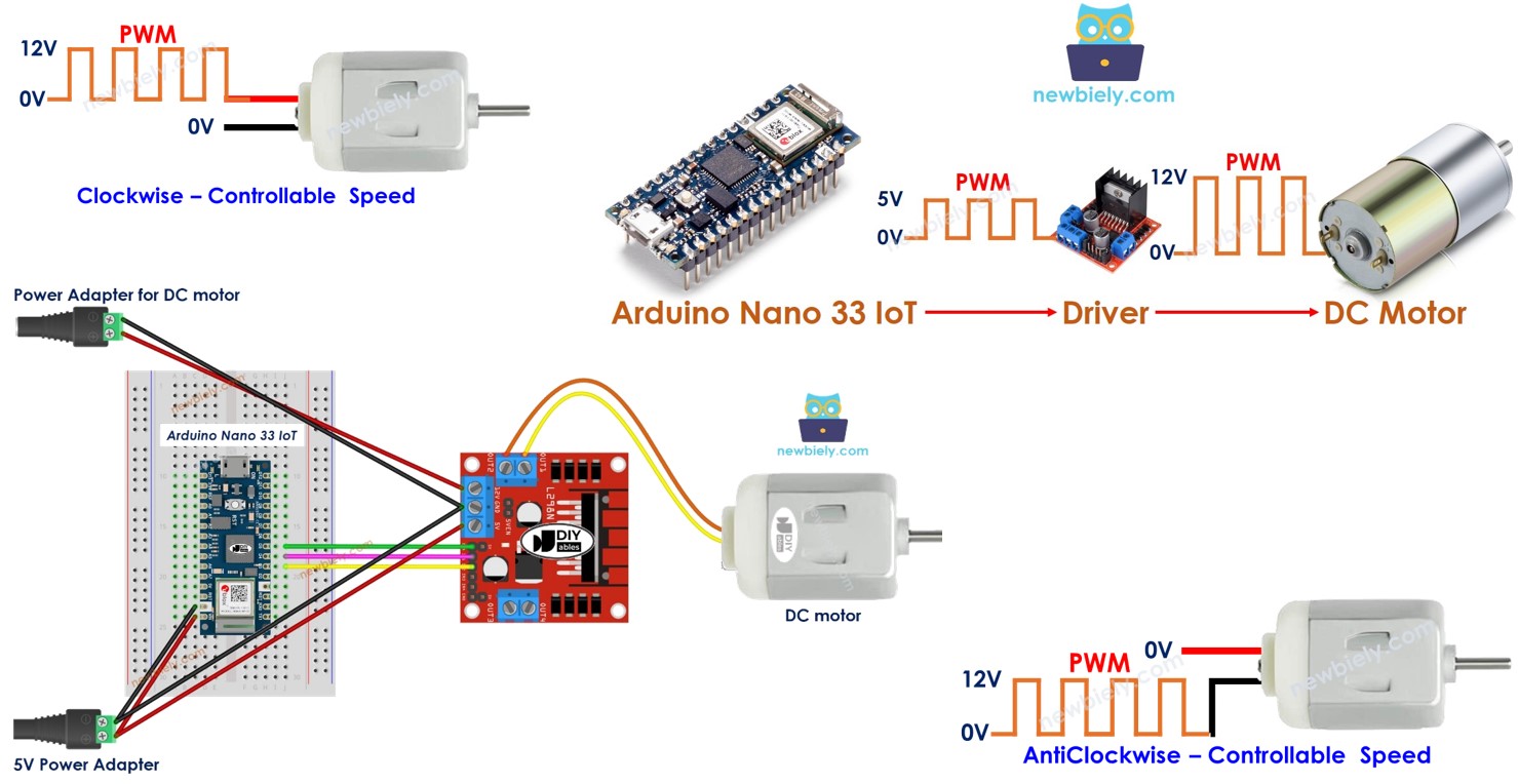
How to control speed and direction of DC motor using Arduino Nano 33 IoT
First, the DC motor uses high voltage that can damage the Arduino Nano 33 IoT, so we cannot connect the DC motor directly to it. We need a special hardware driver between the DC motor and the Arduino Nano 33 IoT. This driver has three main jobs:
- Shield the Arduino Nano 33 IoT from high voltage.
- Use the Arduino Nano 33 IoT’s signal to reverse the power supply and change the motor’s direction.
- Boost the PWM signal (both current and voltage) from the Arduino Nano 33 IoT to manage the motor’s speed.
There are many drivers for DC motors. In this tutorial, we will use the L298N driver.
Overview of L298N Driver
One L298N driver can work with two DC motors or one stepper motor. In this guide, we use it to control a DC motor.
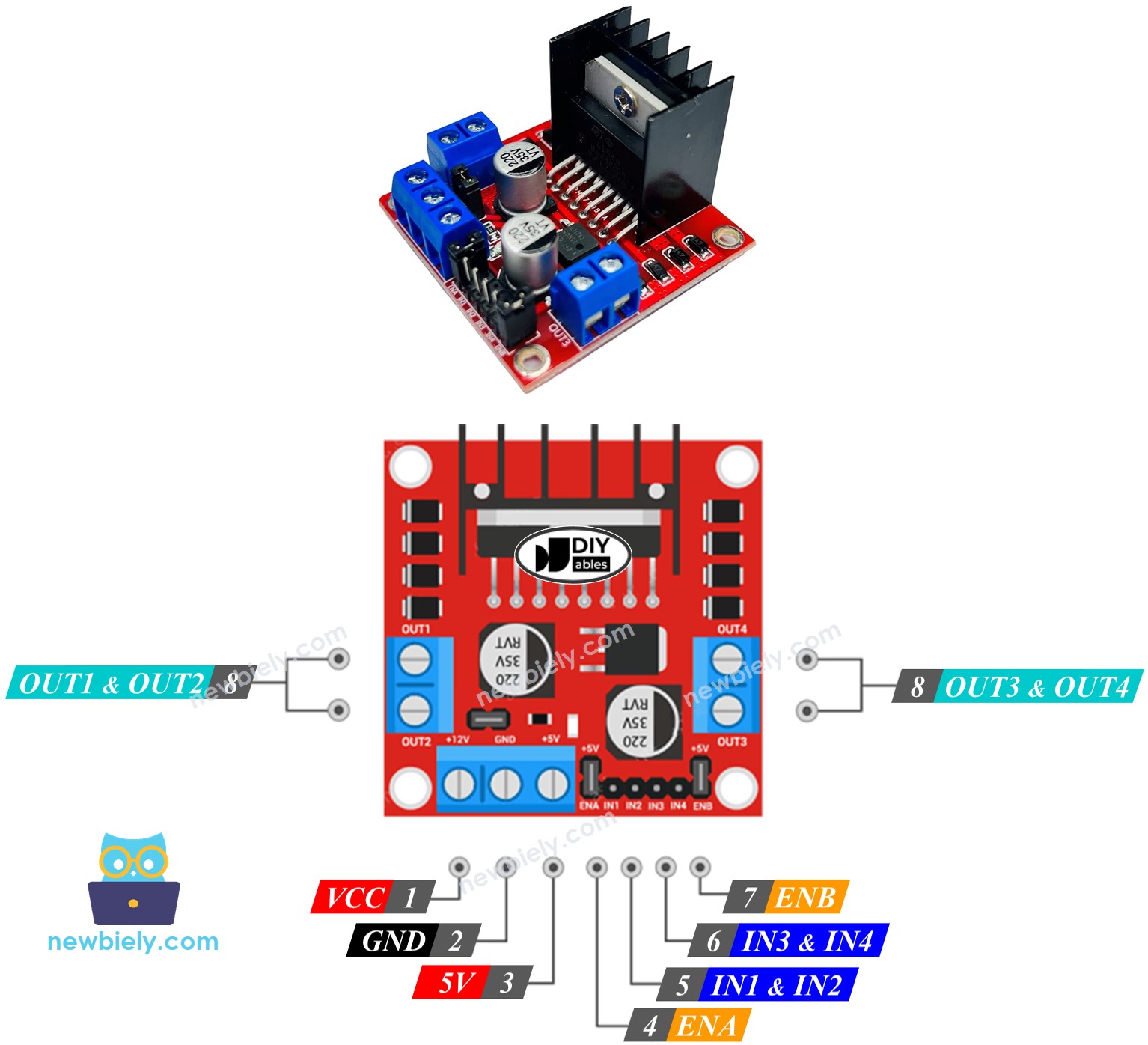
L298N Driver Pinout
The image below shows the pin layout of the L298N driver.
You can find a simple explanation for each pin in this Arduino - DC motor tutorial: https://arduinogetstarted.com/tutorials/arduino-dc-motor#content_about_l298n_driver
One L298N driver can control two DC motors separately.
- Motor A is controlled by the pins IN1, IN2, ENA, OUT1, and OUT2.
- Motor B is controlled by the pins IN3, IN4, ENB, OUT3, and OUT4.
How To Control the Speed of DC Motor via L298N Driver
Controlling the speed of a DC motor is easy. Just send a PWM signal to the ENA/ENB pins on the L298N. You can do this by:
- Connect the Arduino Nano 33 IoT's digital output pin to the ENA/ENB pin on the L298N.
- Use the analogWrite() function to send a PWM signal to the ENA/ENB pin. The L298N driver then boosts the current and voltage before sending the power to the DC motor.
The speed value can be any number from 0 to 255. A speed of 255 makes the motor run as fast as it can, and a speed of 0 stops the motor.
How To Control the Direction of DC Motor via L298N Driver
You can control which way motor A turns by using the IN1 and IN2 pins. The table below shows how the signals on these pins affect the motor's direction.
| IN1 pin | IN2 pin | Direction |
|---|---|---|
| HIGH | LOW | DC Motor A rotates in clockwise direction |
| LOW | HIGH | DC Motor A rotates in anticlockwise direction |
| HIGH | HIGH | DC Motor A stops |
| LOW | LOW | DC Motor A stops |
Also, the table below is for DC motor B.
| IN3 pin | IN4 pin | Direction |
|---|---|---|
| HIGH | LOW | DC Motor B rotates in clockwise direction |
| LOW | HIGH | DC Motor B rotates in anticlockwise direction |
| HIGH | HIGH | DC Motor B stops |
| LOW | LOW | DC Motor B stops |
Let's learn how to create a program to control it. We'll use motor A as an example. Motor B works the same way.
- Set motor A to spin clockwise.
- Turn motor A to spin counterclockwise.
※ NOTE THAT:
If you connect the wires from the DC motor to the L298N driver the wrong way, the motor will move in the opposite direction. To fix it, swap the OUT1 and OUT2 pins.
How To Stop DC Motor
You can stop a DC motor in two ways.
- Set the speed to 0.
- Set both IN1 and IN2 pins to either a low level or a high level.
- Or
How to control a DC motor using L298N driver.
Wiring Diagram
The L298N board has three jumpers. Remove them all before you connect any wires.
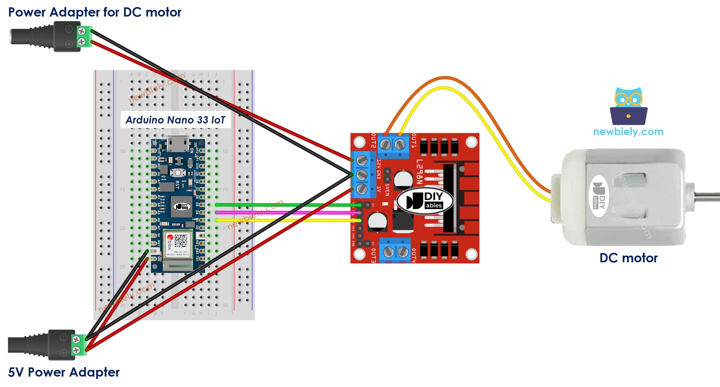
This image is created using Fritzing. Click to enlarge image
Arduino Nano 33 IoT Code
Let's look at the code below that does these tasks one by one.
- The Arduino Nano 33 IoT makes the DC motor go faster.
- The Arduino Nano 33 IoT reverses the DC motor's direction.
- The Arduino Nano 33 IoT makes the DC motor go slower.
- The Arduino Nano 33 IoT stops the DC motor.
Detailed Instructions
If you are new to the Arduino Nano 33 IoT, be sure to check out our Getting Started with Arduino Nano 33 IoT tutorial. Then, follow these steps:
- Connect the components to the Arduino Nano 33 IoT board as depicted in the diagram.
- Use a USB cable to connect the Arduino Nano 33 IoT board to your computer.
- Launch the Arduino IDE on your computer.
- Select the Arduino Nano 33 IoT board and choose its corresponding COM port.
- Take off all three jumpers from the L298N board.
- Copy the code above and paste it into the Arduino IDE.
- Click the Upload button in the Arduino IDE to compile and send the code to the Arduino Nano 33 IoT board.
- Watch the DC motor and you will notice:
- The motor speeds up and spins at full power for 2 seconds.
- The motor then changes direction.
- The motor spins backward at full power for 2 seconds.
- The motor slows down.
- The motor stops for 2 seconds.
- This sequence repeats over and over again.
※ NOTE THAT:
This guide shows you how to change the speed of a DC motor. If you want to set an exact speed (rotations per second), you need to use a PID controller with feedback from an encoder.
How to Control two DC Motors using L298N Driver
Coming soon.