Arduino Nano 33 IoT - Temperature Humidity Sensor
This guide shows how to use the Arduino Nano 33 IoT to get temperature and humidity readings from DHT11 or DHT22 sensors and display them on the Serial Monitor.
Hardware Preparation
Or you can buy the following kits:
| 1 | × | DIYables Sensor Kit (18 sensors/displays) |
Additionally, some of these links are for products from our own brand, DIYables .
Overview of DHT11 and DHT22 Temperature and Humidity Sensor
In summary, the DHT22 sensor is more precise and covers a wider range, but it is also more expensive than the DHT11. Let's explore what they have in common and how they are different.
The commons
- The pin setup is the same
- The wiring for the Arduino Nano 33 IoT is the same
- The Arduino Nano 33 IoT code is very similar
The differences
The table below shows the detailed differences between DHT11 and DHT22.
| DHT22 | DHT11 | |
|---|---|---|
| The price | low cost | ultra low cost |
| The humidity range | 0% to 100% | 20% to 80% |
| The humidity accuracy | ± 2% to 5% | 5% |
| The temperature range | -40°C to 80°C | 0°C to 50°C |
| The temperature accuracy | ± 0.5°C | ± 2°C |
| The reading rate | 0.5Hz (one time per 2 seconds) | 1Hz (one time per second) |
| Dimension | 15.1mm x 25mm x 7.7mm | 15.5mm x 12mm x 5.5mm |
| Operating Voltage | 3 to 5V | 3 to 5V |
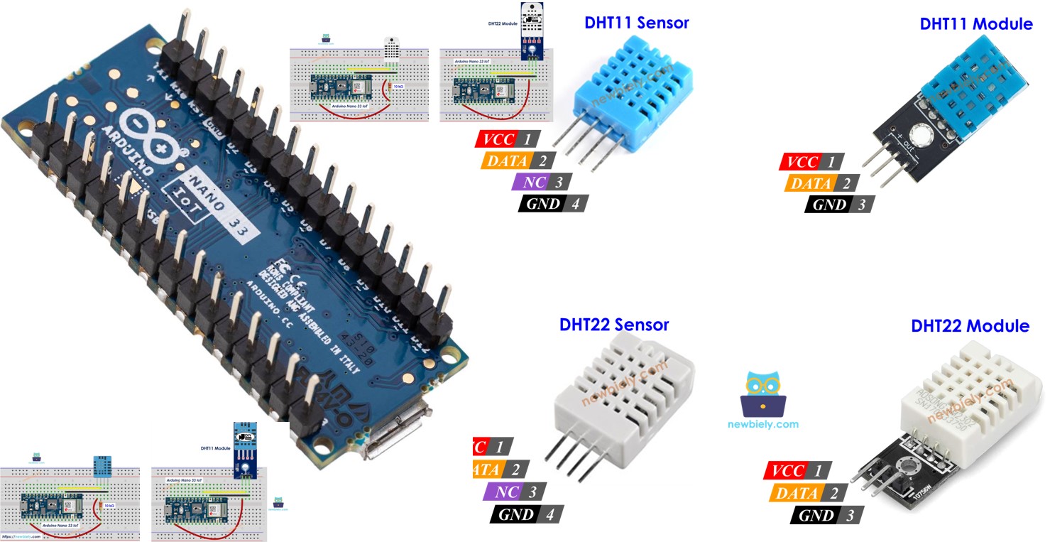
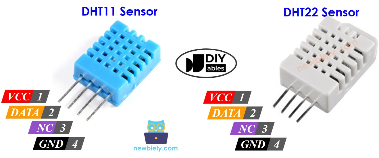
DHT11 and DHT22 Pinout
The DHT11 and DHT22 sensors have four pins.
- GND pin: Connect this pin to the ground (0V).
- VCC pin: Connect this pin to the power supply (3.3V or 5V).
- DATA pin: Use this pin to send and receive information between the sensor and the Arduino Nano 33 IoT.
- NC pin: This pin is not used.
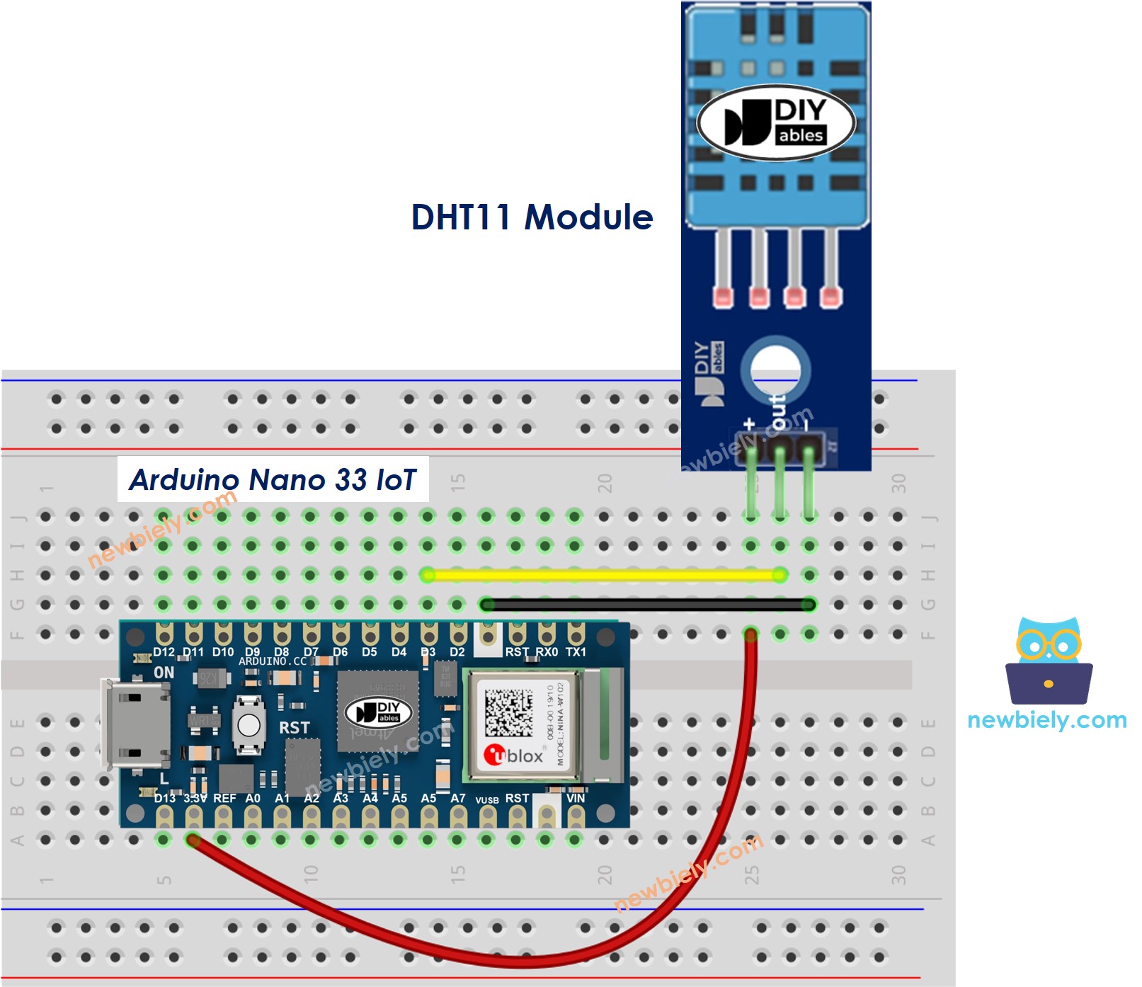
We highly suggest using the DHT11 and DHT22 sensor modules. These modules have a built-in resistor and only three pins: one for power (VCC or +), one for ground (GND or -), and one for data (DATA or OUT).
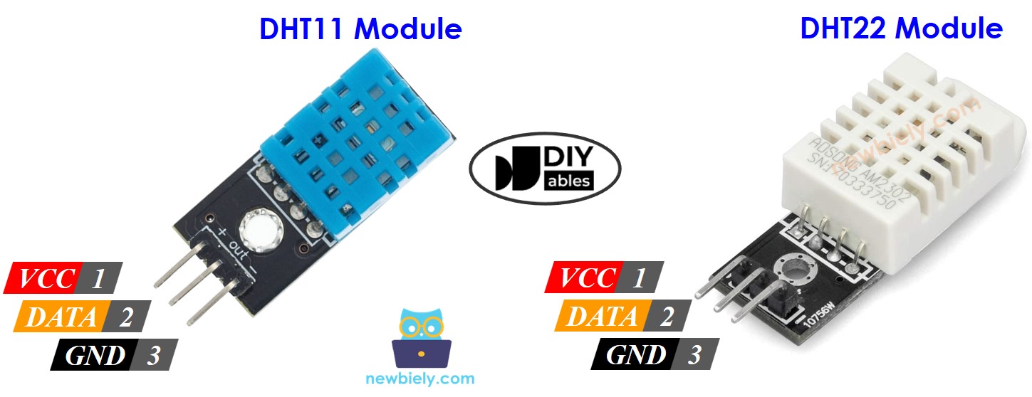
Different companies might put the pins in a different order. Please look carefully at the pin labels printed on the module.
Wiring Diagram between DHT11/DHT22 and Arduino Nano 33 IoT
The wiring for both sensors to the Arduino Nano 33 IoT is the same. They need a resistor between 5K and 10K ohms to keep the data line turned on and to help the sensor talk to the Arduino Nano 33 IoT.
Arduino Nano 33 IoT - DHT11 Sensor Wiring
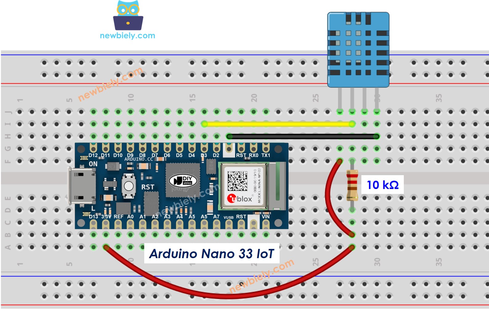
This image is created using Fritzing. Click to enlarge image
Arduino Nano 33 IoT - DHT22 Sensor Wiring
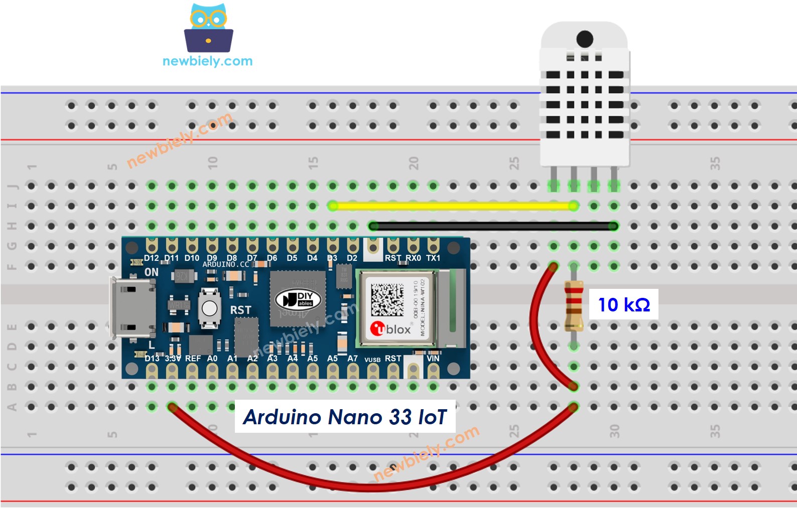
This image is created using Fritzing. Click to enlarge image
Arduino Nano 33 IoT - DHT11 Module Wiring
Most DHT22 sensor modules already include a resistor, so you don't have to add one. This makes the wiring and soldering easier.
This image is created using Fritzing. Click to enlarge image
Arduino Nano 33 IoT - DHT22 Module Wiring
Most DHT22 sensor modules already include a resistor, so you don't have to add one. This saves you some wiring or soldering work.
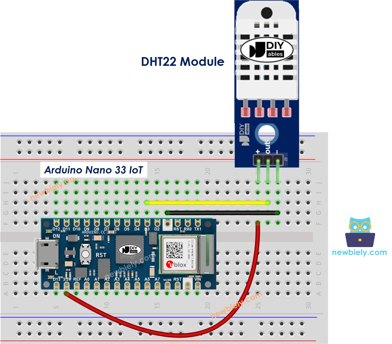
This image is created using Fritzing. Click to enlarge image
Arduino Nano 33 IoT Code - DHT11
Arduino Nano 33 IoT Code - DHT22
The two codes above are different by only one line.
Detailed Instructions
If you are new to the Arduino Nano 33 IoT, be sure to check out our Getting Started with Arduino Nano 33 IoT tutorial. Then, follow these steps:
- Connect the components to the Arduino Nano 33 IoT board as depicted in the diagram.
- Use a USB cable to connect the Arduino Nano 33 IoT board to your computer.
- Launch the Arduino IDE on your computer.
- Select the Arduino Nano 33 IoT board and choose its corresponding COM port.
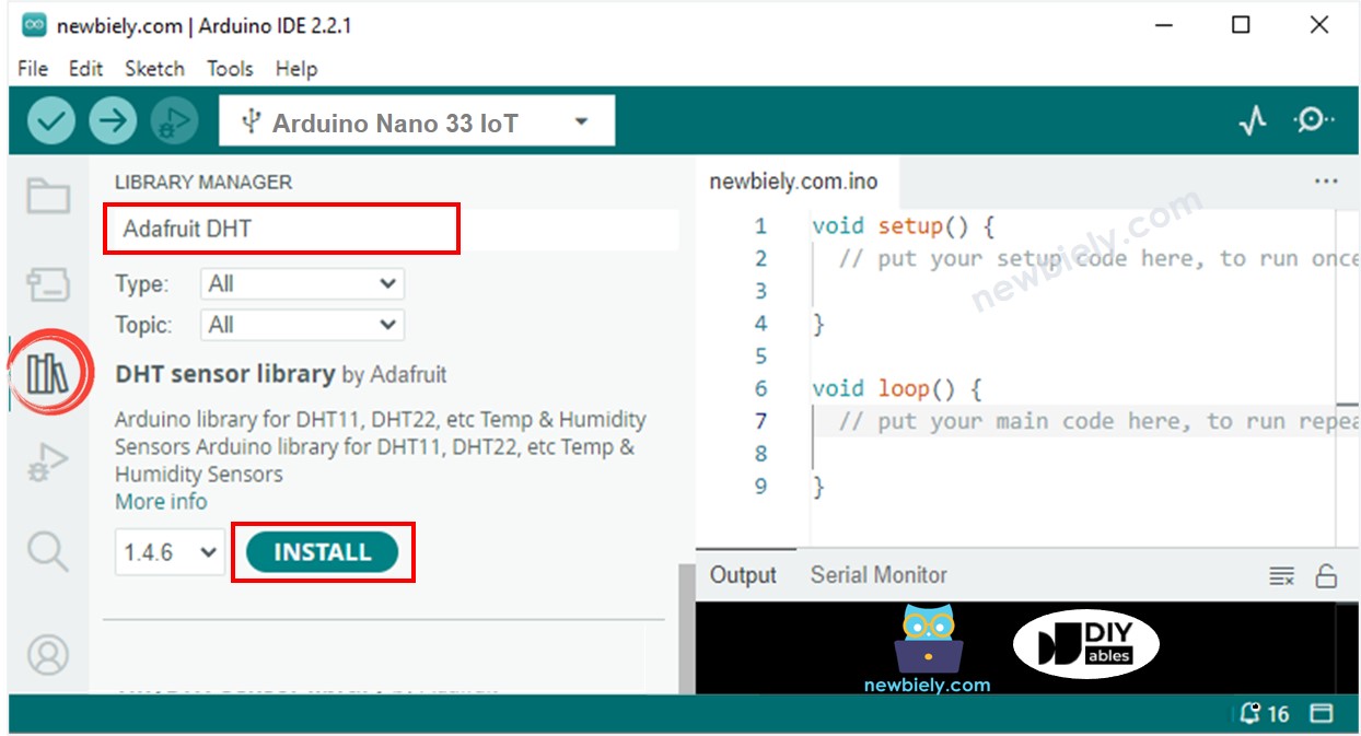
- Open the Library Manager by clicking the Library Manager icon on the left side of the Arduino IDE.
- Type Adafruit DHT in the search box and find the DHT sensor library by Adafruit.
- Click the Install button to install the library.
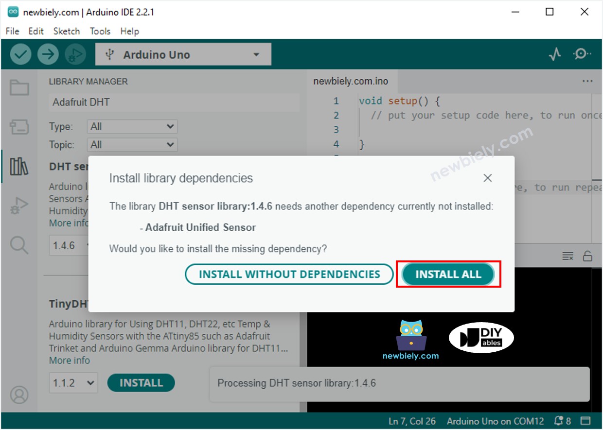
- A window might pop up asking if you want to install the components for the library.
- Click the Install All button to add all the required components.
- Copy one of the codes above and open it with the Arduino IDE. Click the Upload button in the IDE to build and send the code to your Arduino Nano 33 IoT board. Change the sensor's temperature by making it colder or hotter—for example, by placing it near a hot cup of coffee. Then, check the result in the Serial Monitor. It should look like the image below.