Arduino Nano 33 IoT - Button LED
This guide shows you how to use the Arduino Nano 33 IoT and a button to control the LED. We will look at two different examples.
Example 1: Keeping the LED and button states in sync, explained below:
Use-Case 2 - Changing the LED light on or off each time you press the button, explained below:
When the Arduino Nano 33 IoT sees that the button goes from HIGH to LOW (this means you pressed it), it will turn the LED on if it was off, or turn the LED off if it was on. Letting go of the button doesn't change the LED.
In Use-Case 2, it is very important to remove false signals from the button so that everything works correctly. We will show why this is needed by comparing how the LED behaves when we use the Arduino Nano 33 IoT code with and without this button signal cleaning.
Or you can buy the following kits:
Disclosure: Some of the links provided in this section are Amazon affiliate links. We may receive a commission for any purchases made through these links at no additional cost to you.
Additionally, some of these links are for products from our own brand,
DIYables .
Buy Note: Use the LED Module for easier wiring. It includes an integrated resistor.
If you're new to using the LED, Button, and Arduino Nano 33 IoT, please check out these tutorials:
These tutorials explain how LED and Button work, their pinouts, how to connect them to the Arduino Nano 33 IoT, and how to program Arduino Nano 33 IoT to work with the LED and Button.
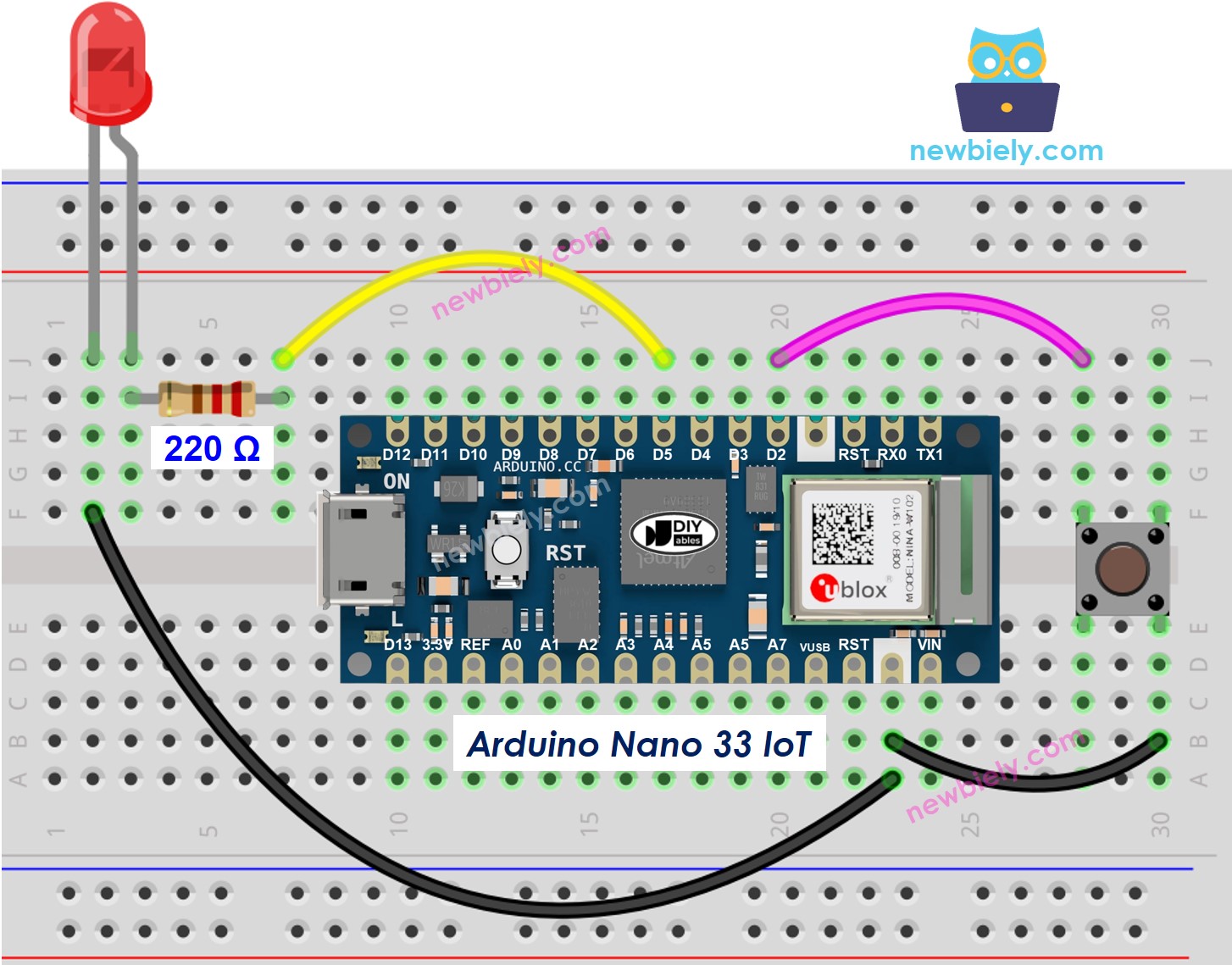
This image is created using Fritzing. Click to enlarge image
※ NOTE THAT:
Please note that the Arduino Nano 33 IoT pins A4 and A5 have built-in pull-up resistors for I2C communication. Although these pins can be used as digital input pins, it is recommended to avoid using them for digital input. If you must use them, do NOT use internal or external pull-down resistors for these pins
#define BUTTON_PIN 2
#define LED_PIN 5
int button_state = 0;
void setup() {
pinMode(LED_PIN, OUTPUT);
pinMode(BUTTON_PIN, INPUT_PULLUP);
}
void loop() {
button_state = digitalRead(BUTTON_PIN);
if(button_state == LOW)
digitalWrite(LED_PIN, HIGH);
else
digitalWrite(LED_PIN, LOW);
}
If you are new to the Arduino Nano 33 IoT, be sure to check out our Getting Started with Arduino Nano 33 IoT tutorial. Then, follow these steps:
Connect the components to the Arduino Nano 33 IoT board as depicted in the diagram.
Use a USB cable to connect the Arduino Nano 33 IoT board to your computer.
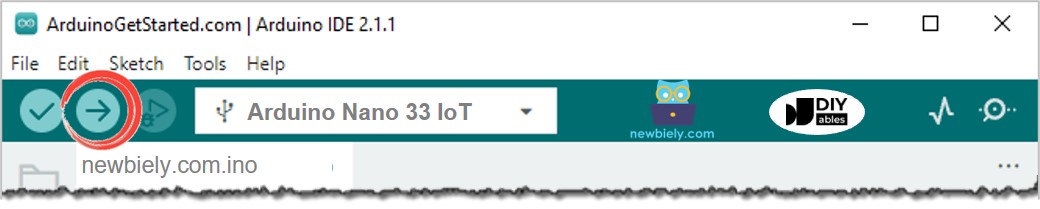
Launch the Arduino IDE on your computer.
Select the Arduino Nano 33 IoT board and choose its corresponding COM port.
Copy the code and paste it into the Arduino IDE.
Click the Upload button in the Arduino IDE to compile and send the code to the board.
You'll notice that the LED light always matches the button's condition.
Look at the step-by-step explanation in the comments of the code!
#define BUTTON_PIN 2
#define LED_PIN 5
int led_state = LOW;
int prev_button_state;
int button_state;
void setup() {
Serial.begin(9600);
pinMode(BUTTON_PIN, INPUT_PULLUP);
pinMode(LED_PIN, OUTPUT);
button_state = digitalRead(BUTTON_PIN);
}
void loop() {
prev_button_state = button_state;
button_state = digitalRead(BUTTON_PIN);
if(prev_button_state == HIGH && button_state == LOW) {
Serial.println("The button is pressed");
led_state = !led_state;
digitalWrite(LED_PIN, led_state);
}
}
You can find the explanation in the comments of the Arduino Nano 33 IoT code above.
In the program, the line "led_state = !led_state" works exactly the same as the code shown below:
if(led_state == LOW)
led_state = HIGH;
else
led_state = LOW;
If you are new to the Arduino Nano 33 IoT, be sure to check out our Getting Started with Arduino Nano 33 IoT tutorial. Then, follow these steps:
Connect the components to the Arduino Nano 33 IoT board as depicted in the diagram.
Use a USB cable to connect the Arduino Nano 33 IoT board to your computer.
Launch the Arduino IDE on your computer.
Select the Arduino Nano 33 IoT board and choose its corresponding COM port.
Copy the code and open it in the Arduino IDE.
Upload the code to your Arduino Nano 33 IoT.
Press the release and button a few times.
Watch how the LED changes.
You might see that the LED light changes each time you press the button. However, this may not happen every time. Sometimes the LED light can switch on and off very quickly with one press, or it might not change at all (it might change twice so fast that you can't really notice it).
To fix this problem, we need to adjust the button so it only sends one signal when pressed. Check out this guide for more details.
Handling button bounce can be hard for beginners. Luckily, the ezButton library makes it simple.
Why is debouncing needed? Check out the Arduino Nano 33 IoT - Button Debounce guide for more details.
#include <ezButton.h>
#define BUTTON_PIN 2
#define LED_PIN 5
ezButton button(BUTTON_PIN);
int led_state = LOW;
void setup() {
Serial.begin(9600);
pinMode(LED_PIN, OUTPUT);
button.setDebounceTime(50);
}
void loop() {
button.loop();
if(button.isPressed()) {
Serial.println("The button is pressed");
led_state = !led_state;
digitalWrite(LED_PIN, led_state);
}
}
If you are new to the Arduino Nano 33 IoT, be sure to check out our Getting Started with Arduino Nano 33 IoT tutorial. Then, follow these steps:
Connect the components to the Arduino Nano 33 IoT board as depicted in the diagram.
Use a USB cable to connect the Arduino Nano 33 IoT board to your computer.
Launch the Arduino IDE on your computer.
Select the Arduino Nano 33 IoT board and choose its corresponding COM port.
Download and install the ezButton library. Follow the instructions at the How To link for help.
Copy the code and open it in the Arduino program.
Click the Upload button in the Arduino program to send the code to the Arduino Nano 33 IoT.
Press and release the button several times.
Watch the LED change its state.
Every time you press the button, the LED light changes its state only once.