Arduino Nano 33 IoT - Flame Sensor
The flame sensor can sense and measure the infrared light that comes from a flame. It is useful for detecting fires and is also called an infrared flame sensor or fire sensor. This sensor gives two kinds of information: one works like a simple switch (on or off) and the other gives an analog signal that shows how strong the flame is.
In this guide, you will learn how to use an Arduino Nano 33 IoT board with a flame sensor to find flames. We will go through the following steps:
- Linking the flame sensor to the Arduino Nano 33 IoT.
- Coding the Arduino Nano 33 IoT to spot fires by checking the sensor's on/off signal.
- Coding the Arduino Nano 33 IoT to see how strong the flame is by checking the sensor's analog signal.
Then you can change the code to make a warning horn sound when a fire is detected.
Hardware Preparation
Or you can buy the following kits:
| 1 | × | DIYables Sensor Kit (18 sensors/displays) |
Additionally, some of these links are for products from our own brand, DIYables .
Overview of Flame Sensor
The infrared flame sensor can find a fire or measure the invisible light the flame gives off. This helps us discover fires. The sensor works with two types of signals: a digital signal and an analog signal.
These sensors are made to pick up certain kinds of infrared light from flames while ignoring other sources, like the heat from people or indoor lights. However, like any sensor, they are not perfect and can sometimes make mistakes—either saying there is a fire when there isn’t (false positive) or missing a fire when there is one (false negative).
Pinout
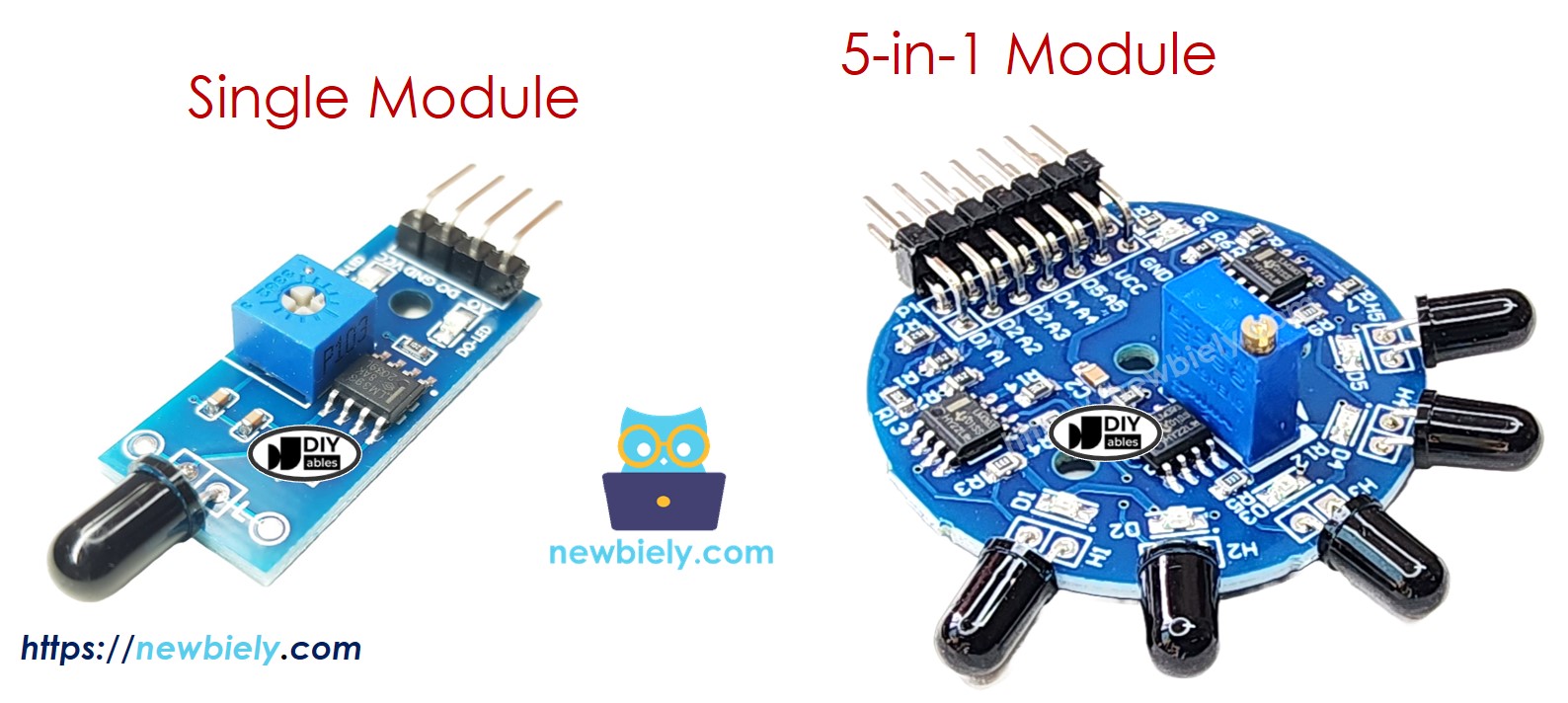
You can find two kinds of flame sensor modules.
A single flame sensor has four pins:
- VCC pin: Connect this pin to a power supply between 3.3V and 5V.
- GND pin: Connect this pin to ground (0V).
- DO pin: This is a digital output pin. It shows HIGH when no flame is detected and LOW when a flame is detected. You can change the flame detection level using the built-in knob.
- AO pin: This is an analog output pin. Its value goes down when the infrared level decreases, and it goes up when the infrared level increases.
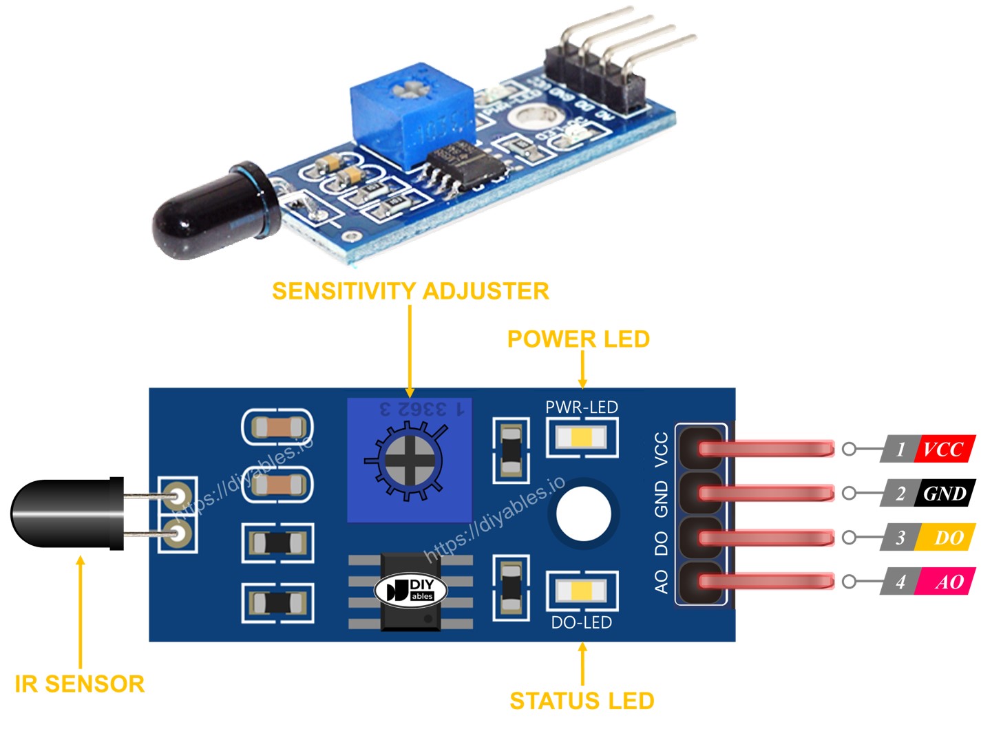
Also, it has two LED lights:
- One LED shows if the system has power.
- One LED connected to the DO pin shows the flame status—it lights up when there is a flame.
The 5-in-1 flame sensor combines five flame sensors on one board. They all share the same potentiometer, VCC, and ground, but each sensor has its own digital output (DO) and analog input (AI) pins and faces a different direction. This setup makes the overall detection range larger.
How It Works
For the digital output (DO) pin:
- The module has a built-in knob that lets you adjust how sensitive the infrared sensor is.
- If the infrared light is stronger than the set limit, the sensor detects a flame, the sensor’s output goes LOW, and the DO-LED lights up.
- If the infrared light is weaker than the set limit, the sensor does not detect a flame, the sensor’s output goes HIGH, and the DO-LED stays off.
About the AO pin:
- When there is a lot of infrared light around, the AO pin shows a high value.
- When there is a little infrared light around, the AO pin shows a low value.
Keep in mind that the knob does not change the value on the AO pin.
Wiring Diagram
The flame sensor module has two outputs. You can use one or both of them based on what you need.
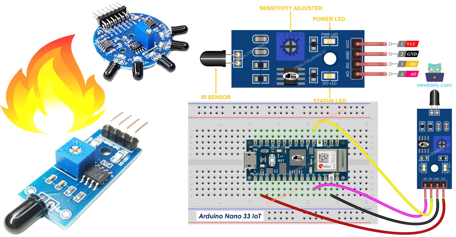
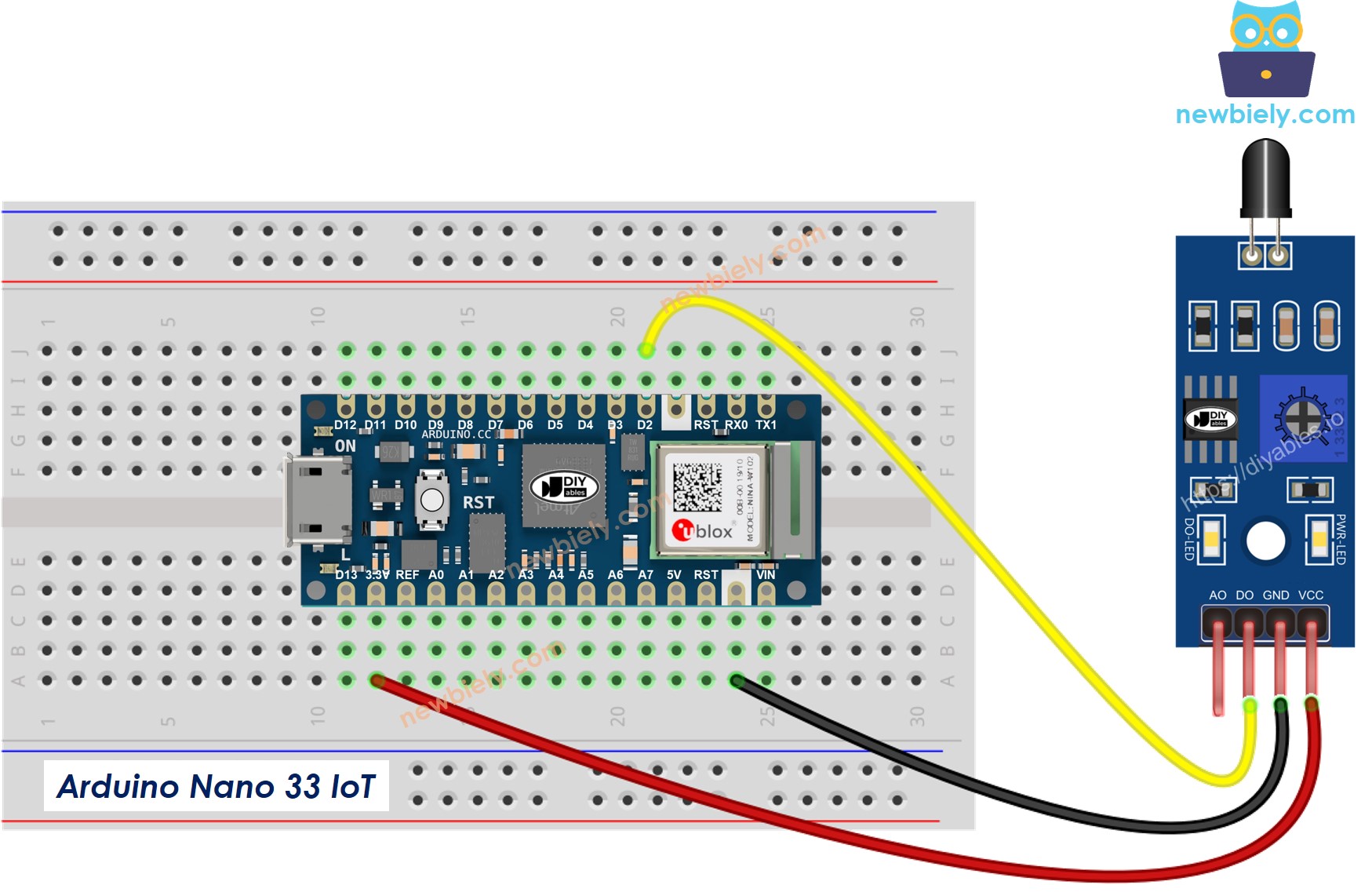
- Wiring diagram showing how to connect the Arduino Nano 33 IoT to a flame sensor using both its analog and digital outputs.
This image is created using Fritzing. Click to enlarge image
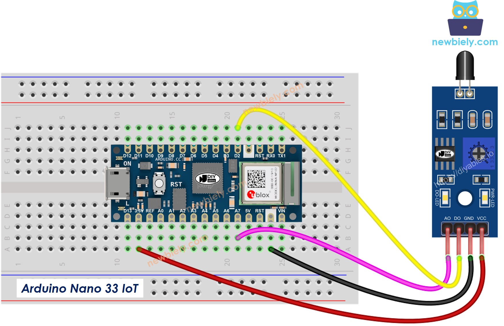
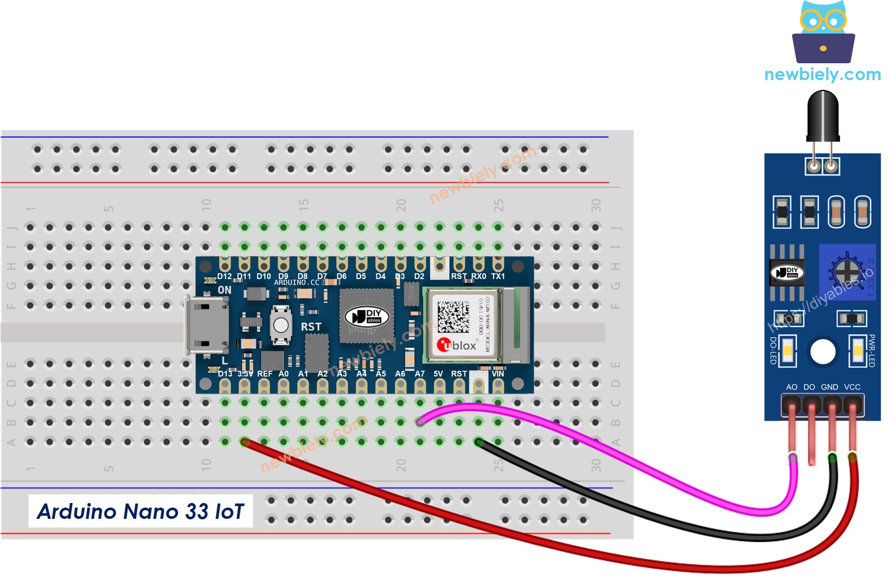
- Simple wiring diagram that shows how to connect the Arduino Nano 33 IoT to the flame sensor using only the digital output (DO).
This image is created using Fritzing. Click to enlarge image
- The connection drawing that shows how to hook up the Arduino Nano 33 IoT and the flame sensor using only AO.
This image is created using Fritzing. Click to enlarge image
※ NOTE THAT:
Please note that the Arduino Nano 33 IoT pins A4 and A5 have built-in pull-up resistors for I2C communication:
- This can affect analog readings, so it is recommended to avoid using these pins with any devices/sensors that relies on ADC.
- Although these pins can be used as digital input pins, it is recommended to avoid using them for digital input. If you must use them, do NOT use internal or external pull-down resistors for these pins.
Arduino Nano 33 IoT Code - Read value from DO pin
Detailed Instructions
If you are new to the Arduino Nano 33 IoT, be sure to check out our Getting Started with Arduino Nano 33 IoT tutorial. Then, follow these steps:
- Connect the components to the Arduino Nano 33 IoT board as depicted in the diagram.
- Use a USB cable to connect the Arduino Nano 33 IoT board to your computer.
- Launch the Arduino IDE on your computer.
- Select the Arduino Nano 33 IoT board and choose its corresponding COM port.
- Copy the code above and open it in the Arduino IDE.
- Click the Upload button to load the code onto your Arduino Nano 33 IoT.
- Point the flame sensor at a flame.
- Check the result in the Serial Monitor.
Remember, if you see that the LED stays on all the time or stays off even when the sensor points at a flame, you can turn the potentiometer to adjust the sensor's sensitivity.
Arduino Nano 33 IoT Code - Read value from AO pin
Detailed Instructions
If you are new to the Arduino Nano 33 IoT, be sure to check out our Getting Started with Arduino Nano 33 IoT tutorial. Then, follow these steps:
- Connect the components to the Arduino Nano 33 IoT board as depicted in the diagram.
- Use a USB cable to connect the Arduino Nano 33 IoT board to your computer.
- Launch the Arduino IDE on your computer.
- Select the Arduino Nano 33 IoT board and choose its corresponding COM port.
- Copy the code above and open it in the Arduino IDE.
- Press the Upload button in the Arduino IDE to send the code to your Arduino Nano 33 IoT.
- Point the flame sensor toward a flame.
- View the result in the Serial Monitor.