Arduino Nano 33 IoT - Light Sensor
This guide shows you how to use the Arduino Nano 33 IoT with a light sensor. We will learn the following steps:
- How a light sensor works.
- How to hook up a light sensor to the Arduino Nano 33 IoT.
- How to write a program for the Arduino Nano 33 IoT that reads values from a light sensor.
Hardware Preparation
Or you can buy the following kits:
| 1 | × | DIYables Sensor Kit (18 sensors/displays) |
Additionally, some of these links are for products from our own brand, DIYables .
The LDR light sensor is very affordable, but it requires a resistor for wiring, which can make the setup more complex. To simplify the wiring, you can use an LDR light sensor module as an alternative.
Overview of Light Sensor
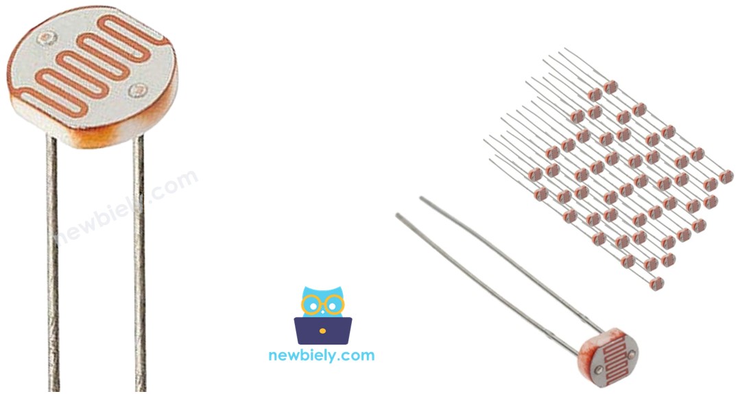
The most popular sensor for measuring light is the photoresistor (also called a photocell or light-dependent resistor, LDR).
It can be used to check if there is light. It can also measure how bright the light is.
Light Sensor Pinout
A light sensor has two pins. Like a normal resistor, you don't need to tell these pins apart.
How Light Sensor Works
A photoresistor's resistance works in the opposite way to the light's brightness. When there is less light on the photoresistor, its resistance becomes higher. So, by checking the resistance of the photoresistor, we can tell how bright the surrounding light is.
WARNING
The value read by the photoresistor gives a rough idea of how strong the light is, but it does not show the exact brightness. This means the photoresistor is not a good choice for tasks that need very precise measurements. Also, some uses need calibration.
Arduino Nano 33 IoT - Light Sensor
The Arduino Nano 33 IoT board's analog input pin changes a voltage (from 0 volts to a reference voltage, usually 3.3V) into a whole number between 0 and 4095. This number is known as the analog value or ADC value. By connecting an analog input pin to a photoresistor, you can use the analogRead() function to read this number.
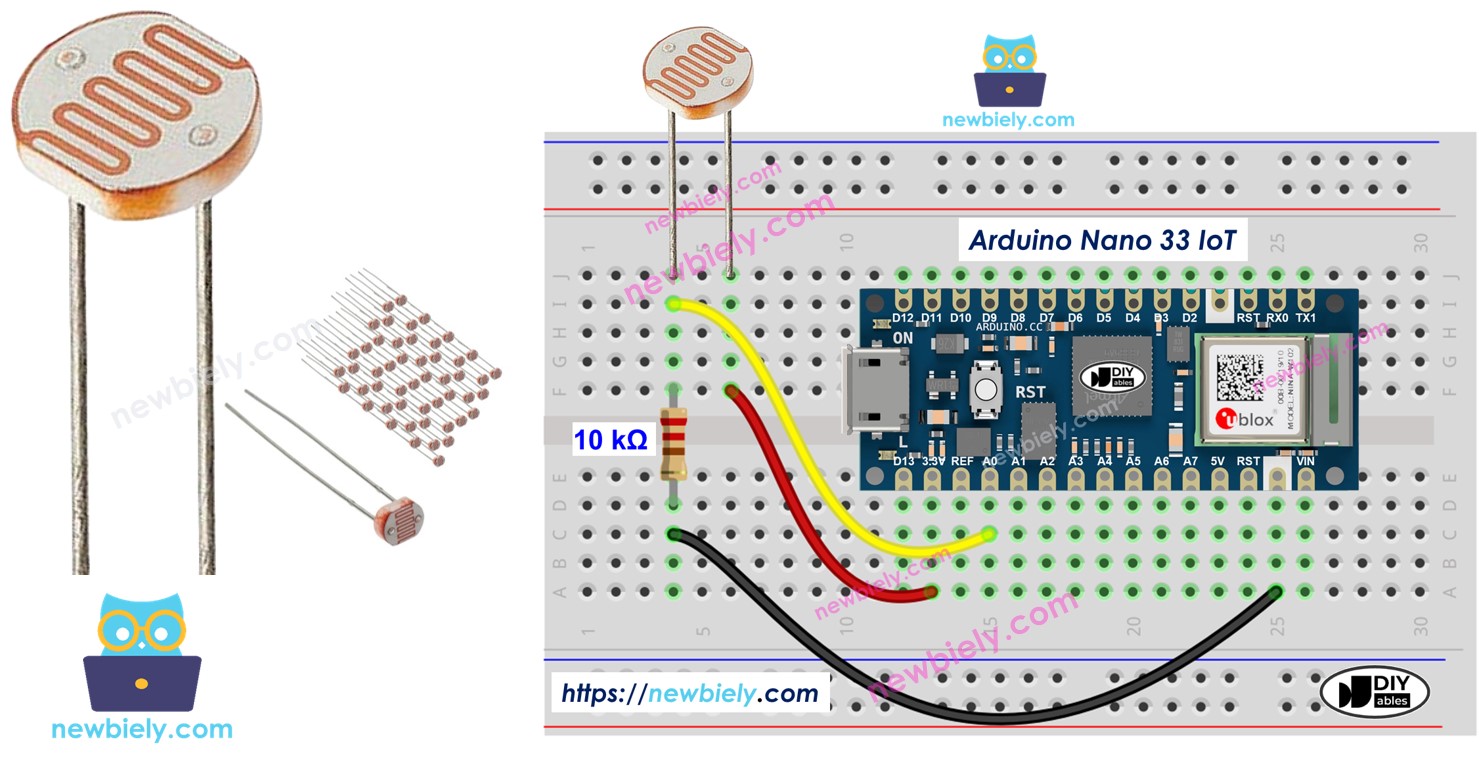
Wiring Diagram between Light Sensor and Arduino Nano 33 IoT
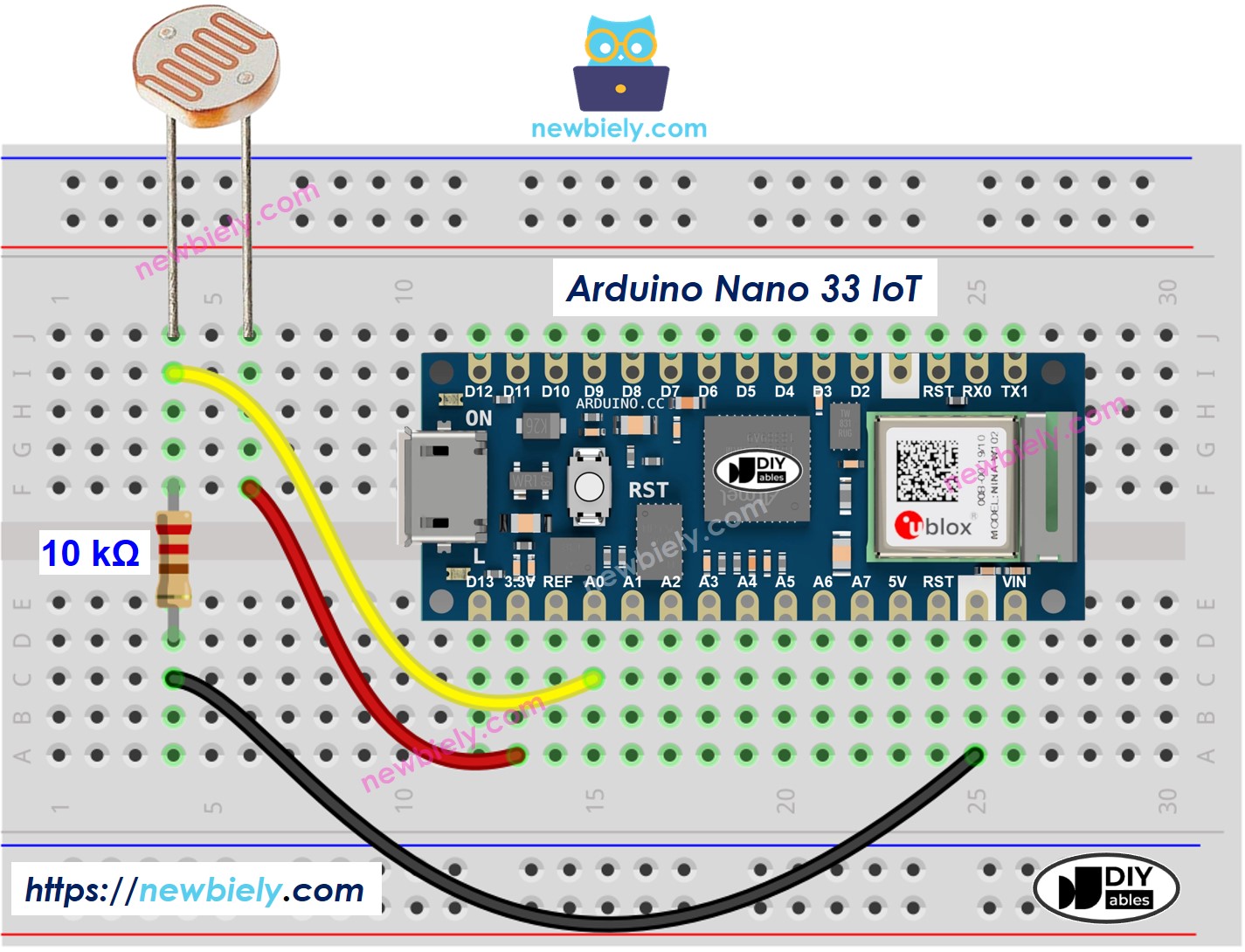
This image is created using Fritzing. Click to enlarge image
Arduino Nano 33 IoT Code
Below is Arduino Nano 33 IoT code that gets a reading from a light sensor and figures out how bright it is.
Detailed Instructions
If you are new to the Arduino Nano 33 IoT, be sure to check out our Getting Started with Arduino Nano 33 IoT tutorial. Then, follow these steps:
- Connect the components to the Arduino Nano 33 IoT board as depicted in the diagram.
- Use a USB cable to connect the Arduino Nano 33 IoT board to your computer.
- Launch the Arduino IDE on your computer.
- Select the Arduino Nano 33 IoT board and choose its corresponding COM port.
- Copy the code above and paste it into the Arduino IDE.
- Click the Upload button on the Arduino IDE to compile and send the code to the Arduino Nano 33 IoT board.
- Open the Serial Monitor in the Arduino IDE.
- Sends light to the sensor
- Look at the output on the Serial Monitor. It appears like this:
Light Sensor and LED
Wiring Diagram
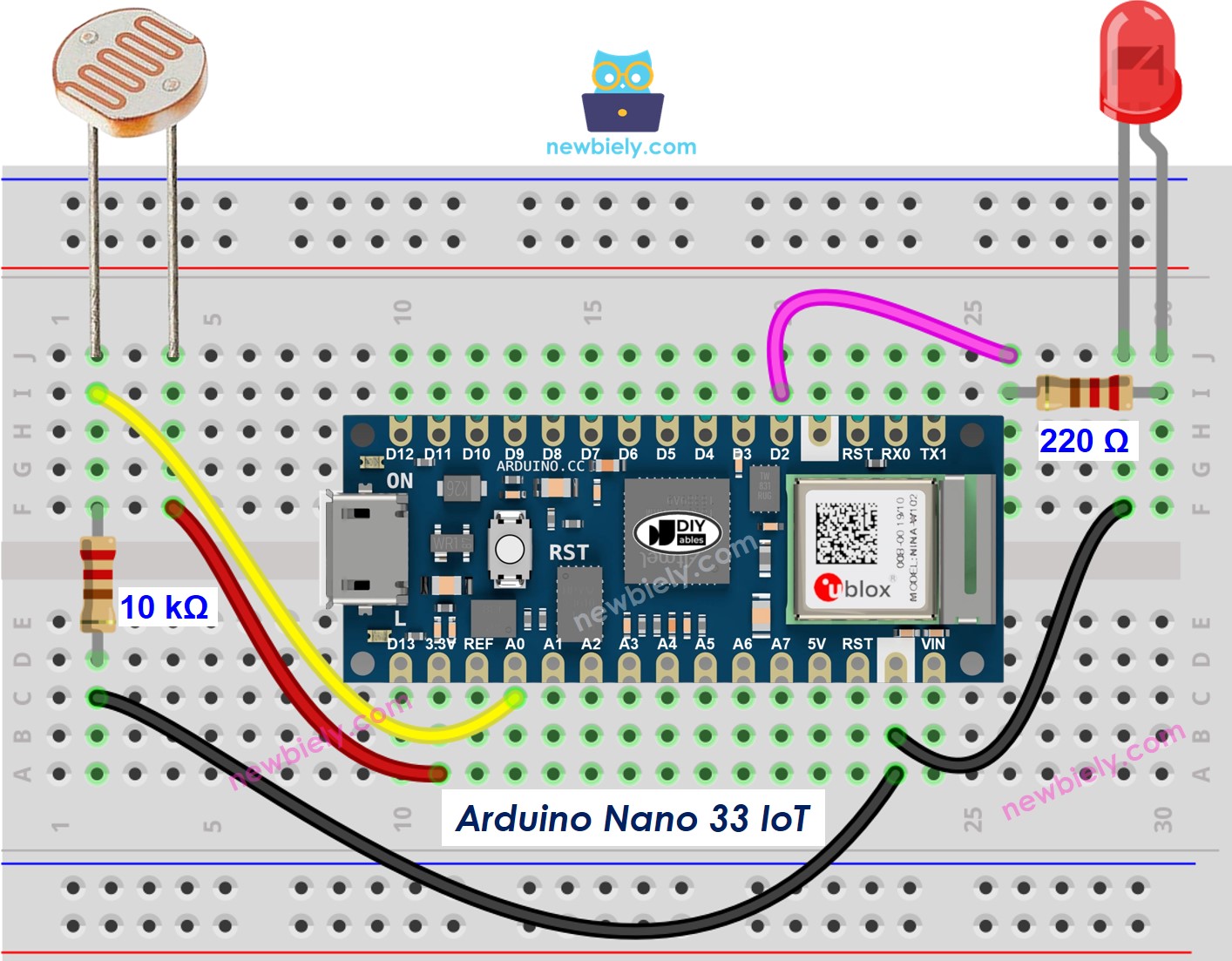
This image is created using Fritzing. Click to enlarge image
Arduino Nano 33 IoT Code
The code below will switch the LED on when it is dark and off when it is light.
※ NOTE THAT:
Please note that the Arduino Nano 33 IoT pins A4 and A5 have built-in pull-up resistors for I2C communication. This can affect analog readings, so it is recommended to avoid using these pins with any devices/sensors that relies on ADC.