Arduino Nano 33 IoT - Buzzer
In this lesson, we’ll learn how to use the Arduino Nano 33 IoT to control a 12V active buzzer that makes a loud noise. If you need to control a 5V active or passive buzzer, please check out this Arduino Nano 33 IoT Piezo Buzzer tutorial.
Hardware Preparation
Or you can buy the following kits:
| 1 | × | DIYables Sensor Kit (18 sensors/displays) |
Additionally, some of these links are for products from our own brand, DIYables .
Overview of 12V Active Buzzer
The 12V active buzzer makes a loud noise, which makes it great for alarm systems.
Pinout
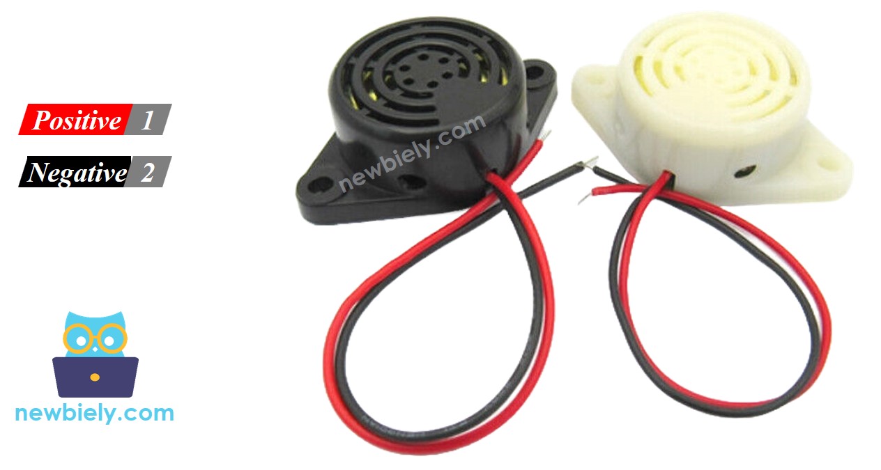
A 12-volt active buzzer normally comes with two pins.
- Negative (-) pin (black): Connect this to the ground (GND) of your DC power supply.
- Positive (+) pin (red): Connect this to the 12V output of your DC power supply.
How to Control 12V Active Buzzer
If you connect a 12V active buzzer to a 12V power supply, it will produce sound. To make the buzzer work with an Arduino Nano 33 IoT, you need to connect a relay between them. The Arduino Nano 33 IoT can control the buzzer through the relay. If you are not sure about what a relay is, how its pins work, or how to program it, check out the Arduino Nano 33 IoT - Relay tutotial.
Wiring Diagram
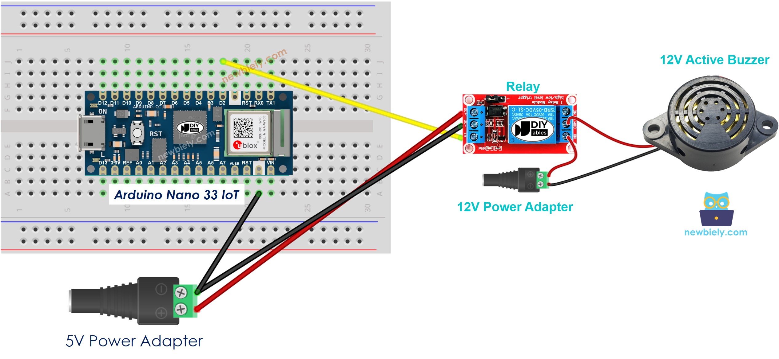
This image is created using Fritzing. Click to enlarge image
Arduino Nano 33 IoT Code
This code repeatedly turns the 12V active buzzer on for one second and then off for two seconds.
Detailed Instructions
If you are new to the Arduino Nano 33 IoT, be sure to check out our Getting Started with Arduino Nano 33 IoT tutorial. Then, follow these steps:
- Connect the components to the Arduino Nano 33 IoT board as depicted in the diagram.
- Use a USB cable to connect the Arduino Nano 33 IoT board to your computer.
- Launch the Arduino IDE on your computer.
- Select the Arduino Nano 33 IoT board and choose its corresponding COM port.
- Copy the code above and paste it into the Arduino IDE.
- Click the Upload button to send the code to the Arduino Nano 33 IoT.
- Check the status of the 12V active buzzer.
Code Explanation
You can find the explanation in the comments of the Arduino code above.