Arduino Nano 33 IoT - Measure Voltage
In this guide, we will show you how to use an Arduino Nano 33 IoT to measure voltage from 0V to 25V with a voltage sensor. We will explain:
- How to set up the voltage sensor with the Arduino Nano 33 IoT
- How to create code for the Arduino Nano 33 IoT to read voltage from the sensor
Hardware Preparation
Or you can buy the following kits:
| 1 | × | DIYables Sensor Kit (18 sensors/displays) |
Additionally, some of these links are for products from our own brand, DIYables .
Overview of Voltage Sensor
A Voltage Sensor is a tool that has a built-in simple circuit to divide voltage, using very accurate resistors to help measure voltage easily. It contains two resistors: one is 30 KΩ and the other is 7.5 KΩ. If the ADC uses a 5V reference, this sensor can measure voltages from 0 to 25V DC. When the ADC uses a 3.3V reference, the sensor can measure voltages from 0 to 16.5V DC.
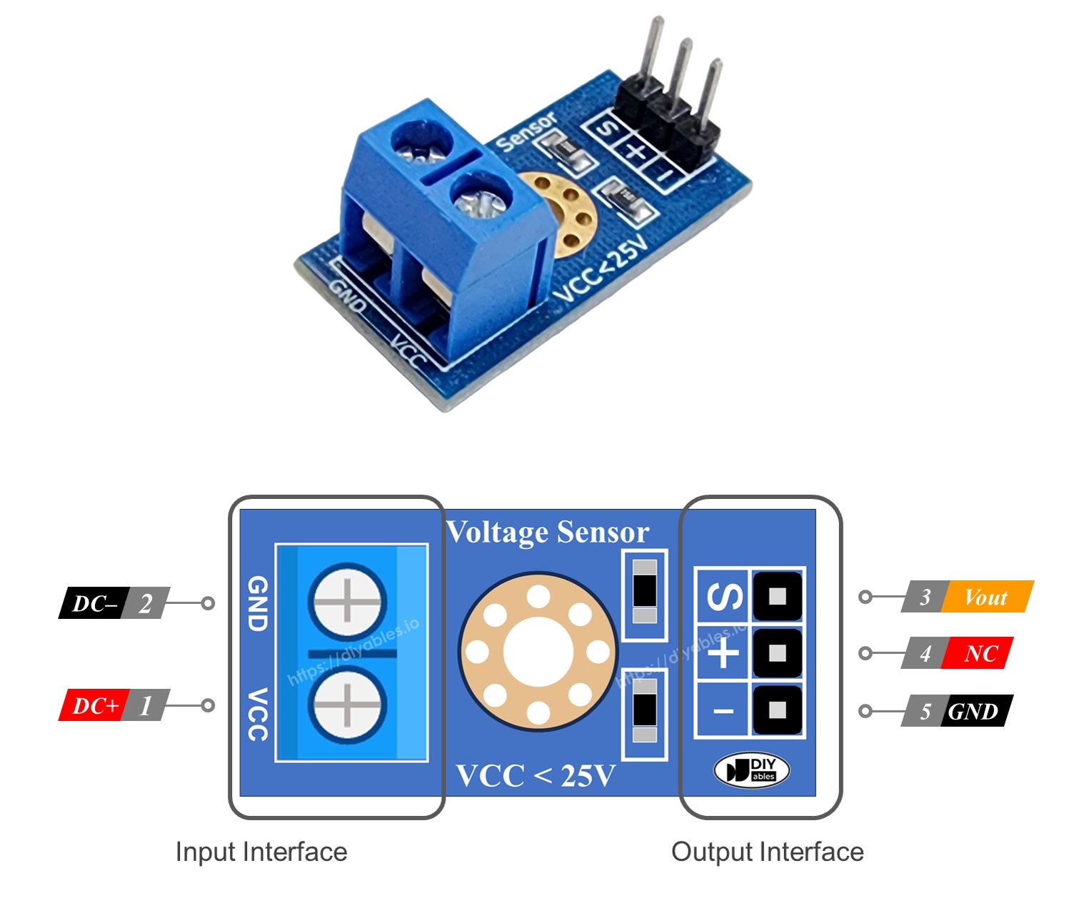
Pinout
A voltage sensor has two groups of pins:
- Input Connection (connect here to measure voltage):
- VCC pin: Connect this positive pin to the high voltage side.
- GND pin: Connect this negative pin to the low voltage side.
- Output Connection (connect this to the Arduino Nano 33 IoT):
- Vout pin (S): Connect this pin to one of the Arduino Nano 33 IoT's analog pins.
- NC pin (+): Do not connect this; leave it unconnected.
- GMS pin (-): Connect this pin to the Arduino Nano 33 IoT's GND (0V).
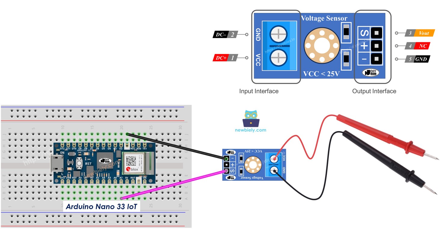
Wiring Diagram
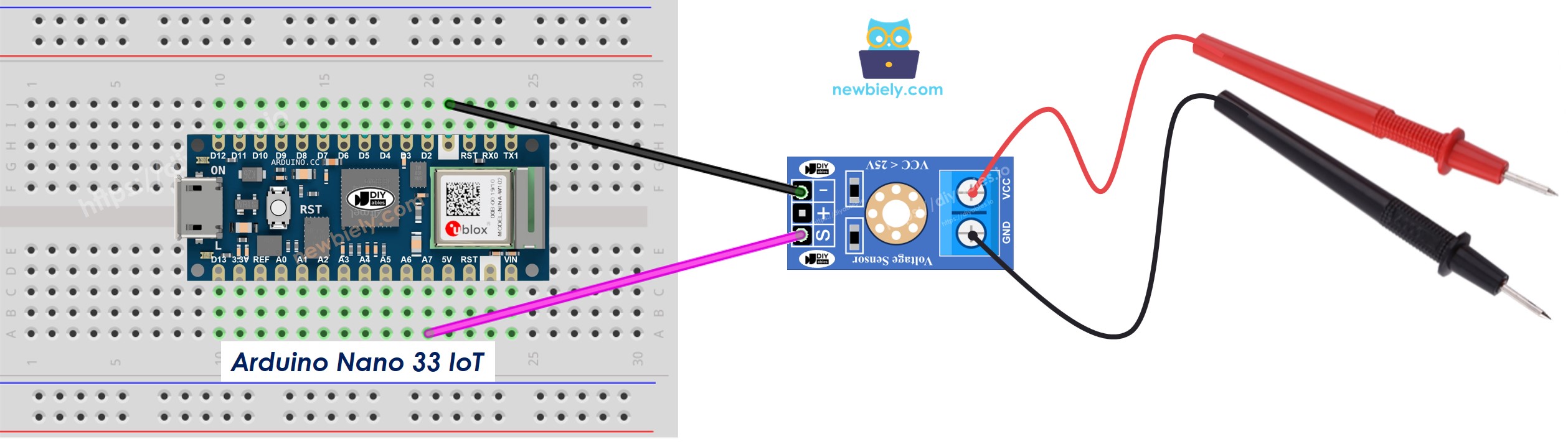
This image is created using Fritzing. Click to enlarge image
※ NOTE THAT:
Please note that the Arduino Nano 33 IoT pins A4 and A5 have built-in pull-up resistors for I2C communication:
- This can affect analog readings, so it is recommended to avoid using these pins with any devices/sensors that relies on ADC.
- Although these pins can be used as digital input pins, it is recommended to avoid using them for digital input. If you must use them, do NOT use internal or external pull-down resistors for these pins.
Arduino Nano 33 IoT Code
Detailed Instructions
If you are new to the Arduino Nano 33 IoT, be sure to check out our Getting Started with Arduino Nano 33 IoT tutorial. Then, follow these steps:
- Connect the components to the Arduino Nano 33 IoT board as depicted in the diagram.
- Use a USB cable to connect the Arduino Nano 33 IoT board to your computer.
- Launch the Arduino IDE on your computer.
- Select the Arduino Nano 33 IoT board and choose its corresponding COM port.
- Copy the code above and paste it into the Arduino IDE.
- Click the Upload button in the Arduino IDE to send the code to the Arduino Nano 33 IoT.
- Check by measuring the 5V and 3.3V outputs on the Arduino Nano 33 IoT.
- Look at the results in the Serial Monitor.
※ NOTE THAT:
The reading may change because the common voltage level is 5 volts. This level might not always be steady and can shift depending on the power source.