Arduino Nano 33 IoT - Door Lock System using Password

This guide explains how to use an Arduino Nano 33 IoT, a keypad, and an electromagnetic lock to build a door lock system. When you enter a password on the keypad, the system checks its correctness. If the password is right, the Arduino Nano 33 IoT sends a signal to the electromagnetic lock that opens the door. The guide also shows you how to add an LCD for extra convenience. The code for the Arduino Nano 33 IoT supports multiple passwords.

Arduino Nano 33 IoT door lock system

Hardware Preparation

1×Arduino Nano 33 IoT
1×Micro USB Cable
1×Keypad 3x4
1×Relay
1×Electromagnetic Lock
1×12V Power Adapter
1×Breadboard
1×Jumper Wires
1×Optionally, LCD I2C
1×Optionally, DC Power Jack
1×Recommended: Screw Terminal Expansion Board for Arduino Nano
1×Recommended: Breakout Expansion Board for Arduino Nano
1×Recommended: Power Splitter for Arduino Nano

Or you can buy the following sensor kits:

1×DIYables Sensor Kit (30 sensors/displays)
1×DIYables Sensor Kit (18 sensors/displays)
Disclosure: Some of the links provided in this section are Amazon affiliate links. We may receive a commission for any purchases made through these links at no additional cost to you.
Additionally, some of these links are for products from our own brand, DIYables .

Overview of Keypad, Electromagnetic Lock and LCD

If you're new to using the Keypad, Electromagnetic Lock, LCD, and Arduino Nano 33 IoT, please check out these tutorials:

These tutorials explain how Keypad, Electromagnetic Lock and LCD work, their pinouts, how to connect them to the Arduino Nano 33 IoT, and how to program Arduino Nano 33 IoT to work with the Keypad and Electromagnetic Lock and LCD.

How check the password

  • The special key * is used to start over the password.
  • The special key # is used to finish entering the password.
  • Every key you press, except for * and #, is added to a word.
  • When the # key is pressed, the password entry is done. The Arduino Nano 33 IoT then checks the word against a list of passwords saved before.
  • If the entered password is correct, the door will open.
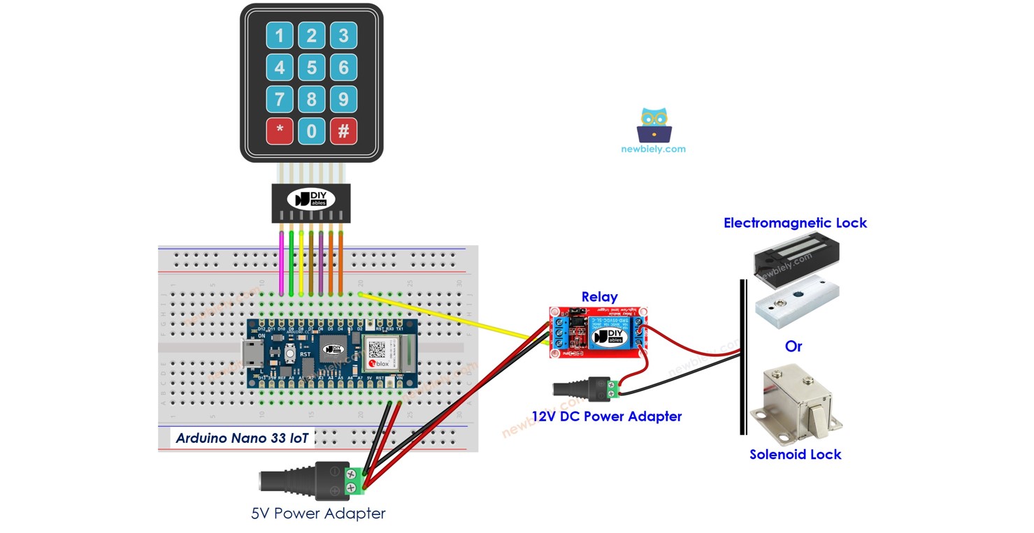
Wiring Diagram

The wiring diagram between Arduino Nano and 33 IoT door lock system

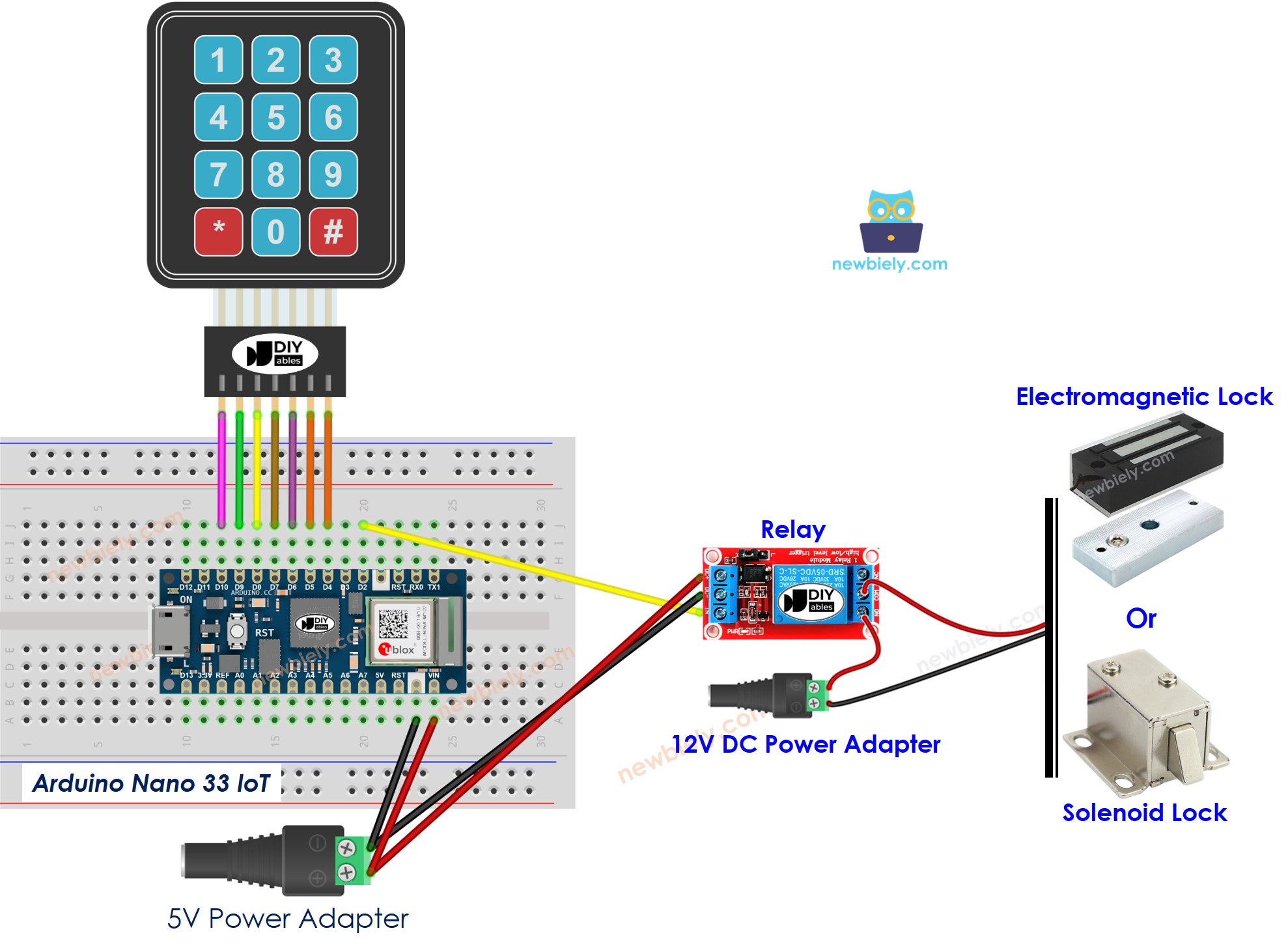
This image is created using Fritzing. Click to enlarge image

Arduino Nano 33 IoT Code - Door lock system with password using keypad, electromagnetic lock

/* * This Arduino Nano 33 IoT code was developed by newbiely.com * * This Arduino Nano 33 IoT code is made available for public use without any restriction * * For comprehensive instructions and wiring diagrams, please visit: * https://newbiely.com/tutorials/arduino-nano-iot/arduino-nano-33-iot-door-lock-system-using-password */ #include <DIYables_Keypad.h> #define RELAY_PIN 2 // The Arduino Nano 33 IoT pin connected to the relay #define ROW_NUM 4 // keypad four rows #define COLUMN_NUM 3 // keypad three columns char keys[ROW_NUM][COLUMN_NUM] = { {'1', '2', '3'}, {'4', '5', '6'}, {'7', '8', '9'}, {'*', '0', '#'} }; byte pin_rows[ROW_NUM] = {10, 9, 8, 7}; // The Arduino Nano 33 IoT pin connected to the row pins byte pin_column[COLUMN_NUM] = {6, 5, 4}; // The Arduino Nano 33 IoT pin connected to the column pins DIYables_Keypad keypad = DIYables_Keypad( makeKeymap(keys), pin_rows, pin_column, ROW_NUM, COLUMN_NUM ); const String password_1 = "1234"; // change your password here const String password_2 = "4444"; // change your password here const String password_3 = "55555"; // change your password here String input_password; void setup() { Serial.begin(9600); input_password.reserve(32); // maximum input characters is 32 pinMode(RELAY_PIN, OUTPUT); digitalWrite(RELAY_PIN, HIGH); // lock the door } void loop() { char key = keypad.getKey(); if (key) { Serial.println(key); if (key == '*') { input_password = ""; // reset the input password } else if (key == '#') { if (input_password == password_1 || input_password == password_2 || input_password == password_3) { Serial.println("Valid Password => unlock the door"); digitalWrite(RELAY_PIN, LOW); // unlock the door for 20 seconds delay(20000); digitalWrite(RELAY_PIN, HIGH); // lock the door } else { Serial.println("Invalid Password => Try again"); } input_password = ""; // reset the input password } else { input_password += key; // append new character to input password string } } }

Detailed Instructions

If you are new to the Arduino Nano 33 IoT, be sure to check out our Getting Started with Arduino Nano 33 IoT tutorial. Then, follow these steps:

  • Connect the components to the Arduino Nano 33 IoT board as depicted in the diagram.
  • Use a USB cable to connect the Arduino Nano 33 IoT board to your computer.
  • Launch the Arduino IDE on your computer.
  • Select the Arduino Nano 33 IoT board and choose its corresponding COM port.
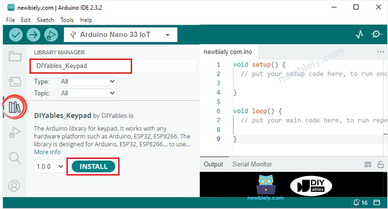
  • Click the Libraries icon on the left side of the Arduino program.
  • Type DIYables_Keypad in the search box and find the keypad library by DIYables.io.
  • Click the Install button to add the keypad library.
Arduino Nano 33 IoT keypad library
  • Copy the code above and paste it into the Arduino IDE.
  • Click the Upload button in the Arduino IDE to compile and send the code to the Arduino Nano 33 IoT board.
  • To test the electromagnet door lock, put the electromagnet close to the metal plate.
  • Press the keys "1111" and then press the "#" key.
  • Observe the force between the electromagnet and the metal plate.
  • Press the keys "1234" and then press the "#" key.
  • Watch the force between the electromagnet and the metal plate again.
  • View the results on the Serial Monitor.
COM6
Send
Invalid Password => Try again Valid Password => unlock the door
Autoscroll Show timestamp
Clear output
9600 baud  
Newline  

Arduino Nano 33 IoT Code - Door lock system with password using keypad, electromagnetic lock and LCD

The code below adds an LCD I2C screen to show the access status. To learn how to wire the LCD, please check this tutorial: Arduino Nano 33 IoT - LCD I2C tutorial

/* * This Arduino Nano 33 IoT code was developed by newbiely.com * * This Arduino Nano 33 IoT code is made available for public use without any restriction * * For comprehensive instructions and wiring diagrams, please visit: * https://newbiely.com/tutorials/arduino-nano-iot/arduino-nano-33-iot-door-lock-system-using-password */ #include <LiquidCrystal_I2C.h> #include <DIYables_Keypad.h> #define RELAY_PIN 2 // The Arduino Nano 33 IoT pin connected to the relay #define ROW_NUM 4 // keypad four rows #define COLUMN_NUM 3 // keypad three columns char keys[ROW_NUM][COLUMN_NUM] = { {'1', '2', '3'}, {'4', '5', '6'}, {'7', '8', '9'}, {'*', '0', '#'} }; byte pin_rows[ROW_NUM] = {10, 9, 8, 7}; // The Arduino Nano 33 IoT pin connected to the row pins byte pin_column[COLUMN_NUM] = {6, 5, 4}; // The Arduino Nano 33 IoT pin connected to the column pins DIYables_Keypad keypad = DIYables_Keypad( makeKeymap(keys), pin_rows, pin_column, ROW_NUM, COLUMN_NUM ); const String password_1 = "1234"; // change your password here const String password_2 = "4444"; // change your password here const String password_3 = "55555"; // change your password here String input_password; LiquidCrystal_I2C lcd(0x27, 16, 2); // I2C address 0x27 (from DIYables LCD), 16 column and 2 rows void setup() { Serial.begin(9600); input_password.reserve(32); // maximum input characters is 32 pinMode(RELAY_PIN, OUTPUT); digitalWrite(RELAY_PIN, HIGH); lcd.init(); // initialize the lcd lcd.backlight(); } void loop() { char key = keypad.getKey(); if (key) { Serial.println(key); if (key == '*') { input_password = ""; // reset the input password lcd.clear(); } else if (key == '#') { lcd.clear(); if (input_password == password_1 || input_password == password_2 || input_password == password_3) { Serial.println("Valid Password => unlock the door"); lcd.setCursor(0, 0); lcd.print("CORRECT!"); lcd.setCursor(0, 1); lcd.print("DOOR UNLOCKED!"); digitalWrite(RELAY_PIN, LOW); // unlock the door for 20 seconds delay(20000); digitalWrite(RELAY_PIN, HIGH); // lock the door } else { Serial.println("Invalid Password => Try again"); lcd.setCursor(0, 0); lcd.print("INCORRECT!"); lcd.setCursor(0, 1); lcd.print("ACCESS DENIED!"); } input_password = ""; // reset the input password } else { if (input_password.length() == 0) { lcd.clear(); } input_password += key; // append new character to input password string lcd.setCursor(input_password.length(), 0); // move cursor to new position lcd.print('*'); // print * key as hiden character } } }

※ NOTE THAT:

The LCD I2C address might be different for each maker. In our code, we used the address 0x27, which is given by the DIYables maker.

Video Tutorial

※ OUR MESSAGES

  • As freelancers, We are AVAILABLE for HIRE. See how to outsource your project to us
  • Please feel free to share the link of this tutorial. However, Please do not use our content on any other websites. We invested a lot of effort and time to create the content, please respect our work!