Arduino Nano 33 IoT - Rotary Encoder
In this guide, you will learn how to work with a rotary encoder using the Arduino Nano 33 IoT. Here is what you will learn:
- What is the difference between a rotary encoder and a potentiometer
- How the rotary encoder works
- How to connect the rotary encoder to the Arduino Nano 33 IoT
- How to write code for the Arduino Nano 33 IoT to read the direction and position from the rotary encoder without using interrupts
- How to write code for the Arduino Nano 33 IoT to read the direction and position from the rotary encoder using interrupts
Hardware Preparation
Or you can buy the following kits:
| 1 | × | DIYables Sensor Kit (18 sensors/displays) |
Additionally, some of these links are for products from our own brand, DIYables .
Overview of Rotary Encoder
A rotating dial, like the one on a radio, can send signals that change into electricity. It shows us how much it has turned and where it is set. There are two main kinds:
- Incremental encoder: It uses quick signals to show how far something has moved.
- Absolute encoder: It gives a unique code for each spot, so you can tell its location even if the power goes off.
This lesson mainly focuses on the first type: the incremental encoder.
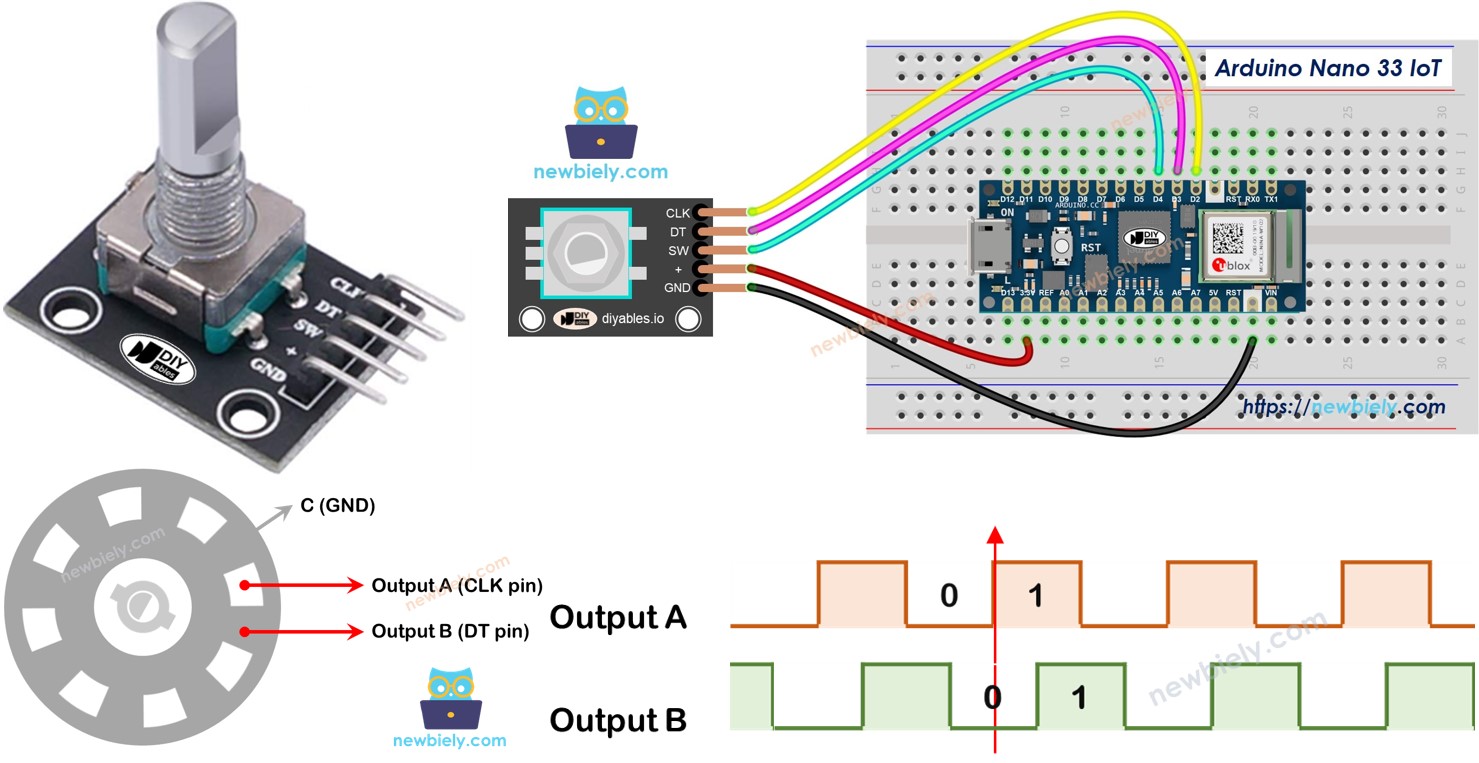
Rotary Encoder Module Pinout
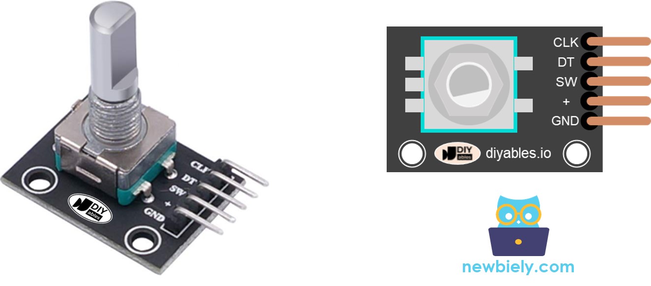
A rotary encoder device has four pins:
- CLK pin (Output A): This is the main signal that tells us how much the knob has turned. Each time you turn the knob one step (click) in any direction, the CLK pin sends a signal that goes from LOW to HIGH and back to LOW.
- DT pin (Output B): This signal works like the CLK pin but is delayed by about 90 degrees. It helps us know whether the knob is turning clockwise or anticlockwise.
- SW pin: This comes from the encoder’s button. It is usually open. When connected with a pull-up resistor, the SW pin reads as HIGH when the knob is not pressed and LOW when it is pressed.
- VCC pin (+): This pin must be connected to the power supply (between 3.3 and 5 volts).
- GND pin: This pin must be connected to the ground (0 volts).
Rotary Encoder vs Potentiometer
You might mix up a rotary encoder and a potentiometer, but they are not the same. Here is a simple comparison between them:
- A rotary encoder is a new type of potentiometer that can do more than the old version.
- A rotary encoder can spin all the way around without stopping, while a potentiometer can only turn about three-quarters of a circle.
- A rotary encoder produces a series of pulses, while a potentiometer gives out a continuous voltage signal.
- A rotary encoder is useful when you only need to know how much the knob has turned, not its exact position. A potentiometer is better when you need to know the precise position of the knob.
How Rotary Encoder Works
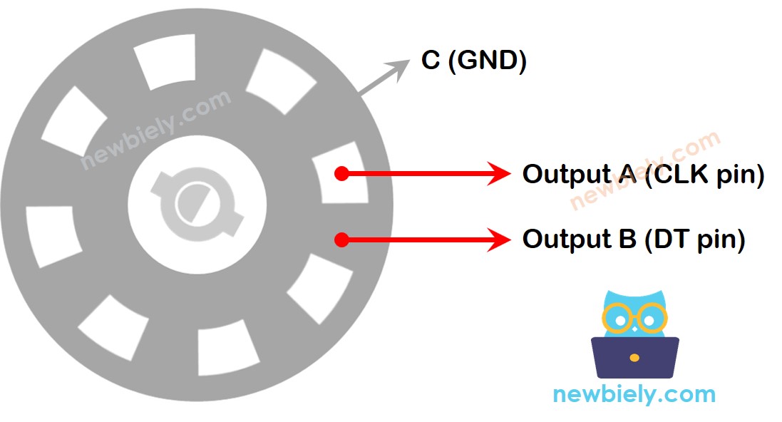
Inside the encoder, there is a small disk with slots. It is connected to a pin called C, which works as a shared ground. There are also two other pins, A and B.
- When you turn the knob, pins A and B meet a common ground pin C. Which one touches first depends on the direction you turn the knob—clockwise or counterclockwise.
- These contacts create two signals. They have slightly different timing because one pin touches the ground before the other. These signals are 90 degrees out of step, which is known as quadrature encoding.
- If you turn the knob clockwise, pin A touches the ground before pin B. If you turn the knob counterclockwise, pin B touches the ground first.
- By watching when each pin touches or leaves the ground, we can tell which way the knob is turning. We do this by checking what happens to pin B whenever pin A makes a change.
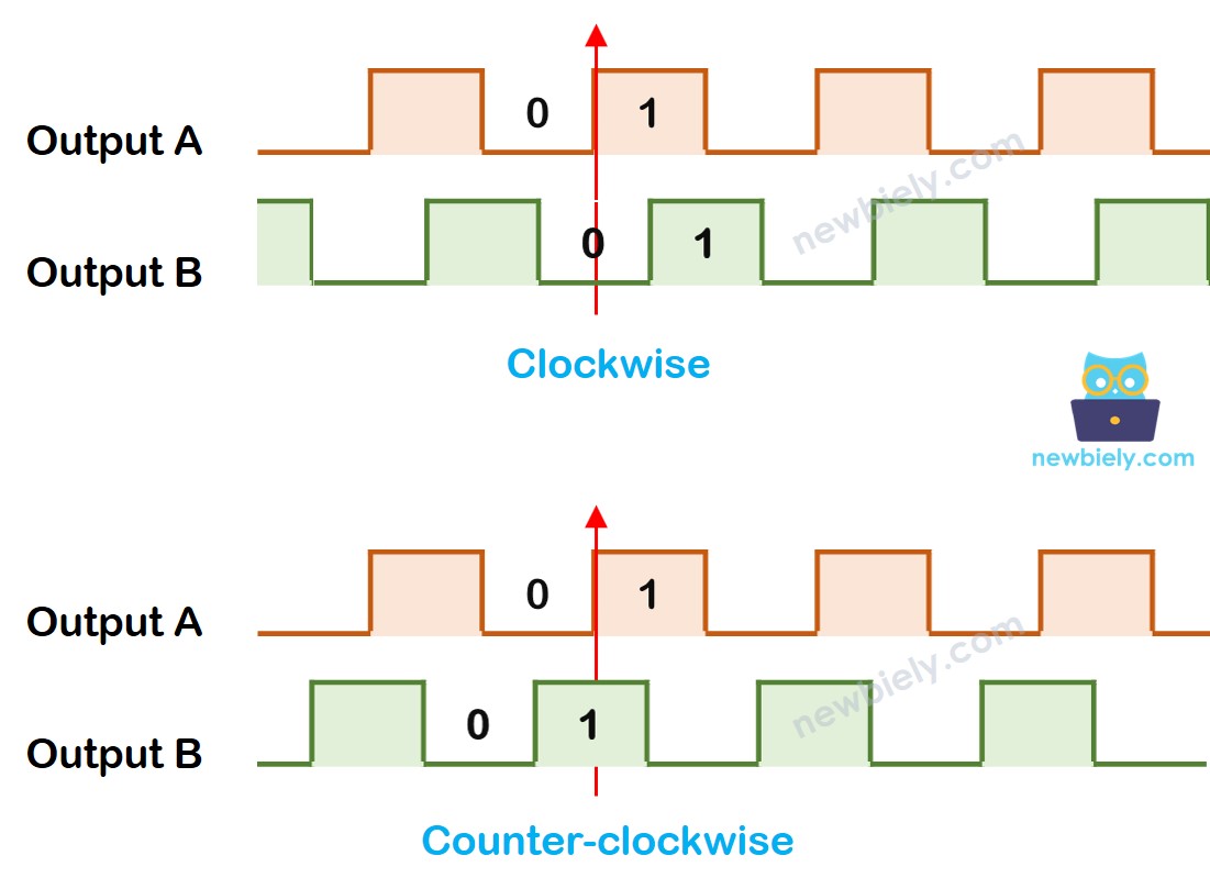
When A switches from a low level to a high level:
- If B is HIGH, turn the knob to the left.
- If B is LOW, turn the knob to the right.
※ NOTE THAT:
Pin A and Pin B are connected to the CLK and DT pins. However, some manufacturers might use a different order. The code below has been tested with the rotary encoder from DIYables.
How To Program For Rotary Encoder
- The Arduino Nano 33 IoT checks the CLK pin for any signals.
- When the signal changes from LOW to HIGH, it then checks the DT pin:
- If the DT pin is HIGH, it means the knob is turned counter-clockwise and the counter goes up by 1.
- If the DT pin is LOW, it means the knob is turned clockwise and the counter goes down by 1.
Wiring Diagram
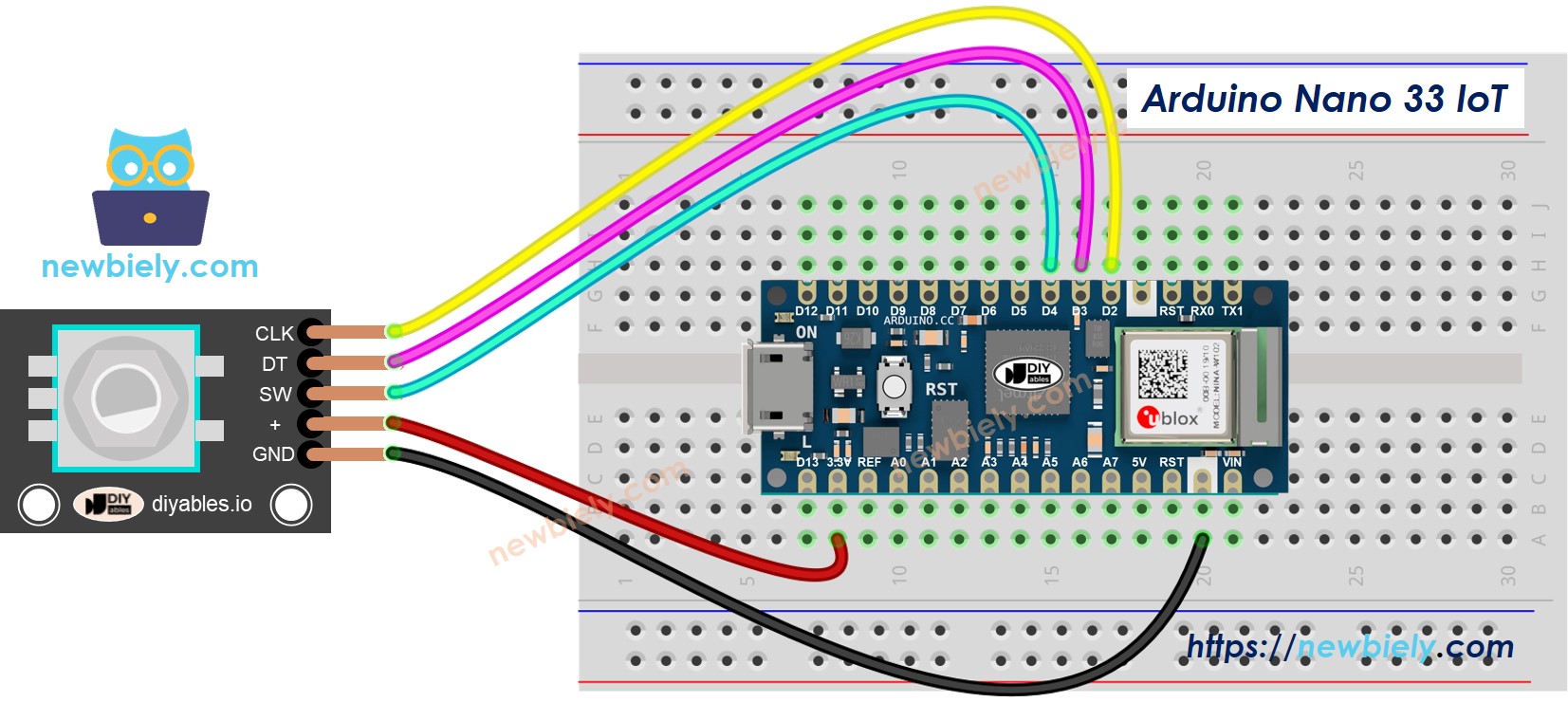
This image is created using Fritzing. Click to enlarge image
※ NOTE THAT:
Please note that the Arduino Nano 33 IoT pins A4 and A5 have built-in pull-up resistors for I2C communication. Although these pins can be used as digital input pins, it is recommended to avoid using them for digital input. If you must use them, do NOT use internal or external pull-down resistors for these pins
Arduino Nano 33 IoT Code – Rotary Encoder
This Arduino Nano 33 IoT code does the following:
- Detects which way and how much the rotary knob is turned.
- When the knob moves one step (click) to the right, the counter increases by one.
- When the knob moves one step (click) to the left, the counter decreases by one.
- Also detects if the button is pressed.
We use the ezButton library to make the button code simpler by eliminating extra signals.
Detailed Instructions
If you are new to the Arduino Nano 33 IoT, be sure to check out our Getting Started with Arduino Nano 33 IoT tutorial. Then, follow these steps:
- Connect the components to the Arduino Nano 33 IoT board as depicted in the diagram.
- Use a USB cable to connect the Arduino Nano 33 IoT board to your computer.
- Launch the Arduino IDE on your computer.
- Select the Arduino Nano 33 IoT board and choose its corresponding COM port.
- Install the ezButton library on your Arduino IDE
- Copy the code above and open it in the Arduino IDE
- Click the Upload button in the Arduino IDE to send the code to your Arduino Nano 33 IoT
- Turn the knob to the right, then to the left
- Press the knob
- Look at the result on the Serial Monitor
Code Explanation
Take a look at the comments next to each line in the code.
Arduino Nano 33 IoT Code – Rotary Encoder with Interrupt
In the earlier code, constantly checking the pin's state uses too many resources on the Arduino Nano 33 IoT and can miss counts if other parts of the program run slowly.
A good solution is to use the interrupt, which avoids the need for polling. This lets the Arduino Nano 33 IoT do other tasks without missing any counts. The code below shows how the Arduino Nano 33 IoT uses the interrupt to read the direction and position from the rotary encoder.
When you turn the knob, you'll see data on the Serial Monitor just like you saw with the earlier code.
※ NOTE THAT:
- Some guides on other sites might tell you to use two interrupts for one encoder, but you only need one.
- Always add the word volatile for global variables used in the interrupt. If you skip this, you might get strange errors.
- Keep the code inside the interrupt as simple as possible. Do not use Serial.print() or Serial.println() in the interrupt.
Arduino Nano 33 IoT Rotary Encoder Application
Using a Rotary Encoder, you can use it for many different tasks, including these:
- Arduino Nano 33 IoT – The rotary knob changes the servo motor's position
- Arduino Nano 33 IoT – The rotary knob adjusts the LED brightness
- Arduino Nano 33 IoT – The rotary knob controls the stepper motor's speed