Arduino Nano 33 IoT - RS485
This guide shows you how to use RS485 communication with the Arduino Nano 33 IoT. We will learn about these topics:
- How to hook up the Arduino Nano 33 IoT with the TTL to RS485 module.
- How to write code for the Arduino Nano 33 IoT to get data from the TTL to RS485 module.
- How to write code for the Arduino Nano 33 IoT to send data to the TTL to RS485 module.
- How to transfer data between your PC and the Arduino Nano 33 IoT using RS485, and the other way around.
Hardware Preparation
Or you can buy the following kits:
| 1 | × | DIYables Sensor Kit (18 sensors/displays) |
Additionally, some of these links are for products from our own brand, DIYables .
Overview of TTL to RS485 Module
When using serial communication on the Arduino Nano 33 IoT with commands like Serial.print(), Serial.read(), and Serial.write(), the data is sent out through the TX pin and received through the RX pin. These pins work at a basic voltage level (TTL) with a limited range. So, if you want to communicate over long distances, you need to change the TTL signal into other standards like RS232, RS485, or RS422.
In this guide, we will learn how to use RS485 (also known as RS-485) with the Arduino Nano 33 IoT using a TTL to RS485 module. This module changes TTL signals into RS485 signals and back, which makes it easier to communicate over long distances.
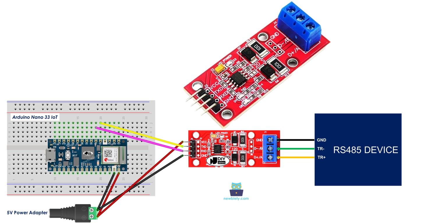
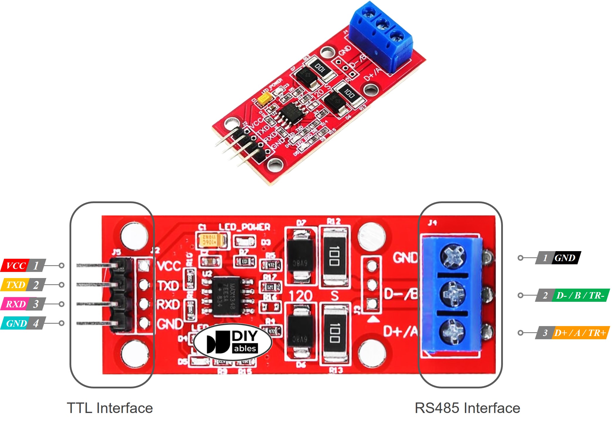
Pinout
The RS485 to TTL module has two ports.
- TTL Interface (connected to Arduino Nano 33 IoT):
- VCC Pin: Connect this power pin to VCC (5V or 3.3V).
- GND Pin: Connect this power pin to GND (0V).
- RXD Pin: Connect this data pin to the TX pin on the Arduino Nano 33 IoT.
- TXD Pin: Connect this data pin to the RX pin on the Arduino Nano 33 IoT.
- RS485 Interface:
- D+ (A or TR+) Pin: This pin is used for sending and receiving data.
- D- (B or TR-) Pin: This pin is used for data transmission.
- GND Pin: This ground pin is optional, but it is best to use it to reduce noise and improve performance.
Wiring Diagram
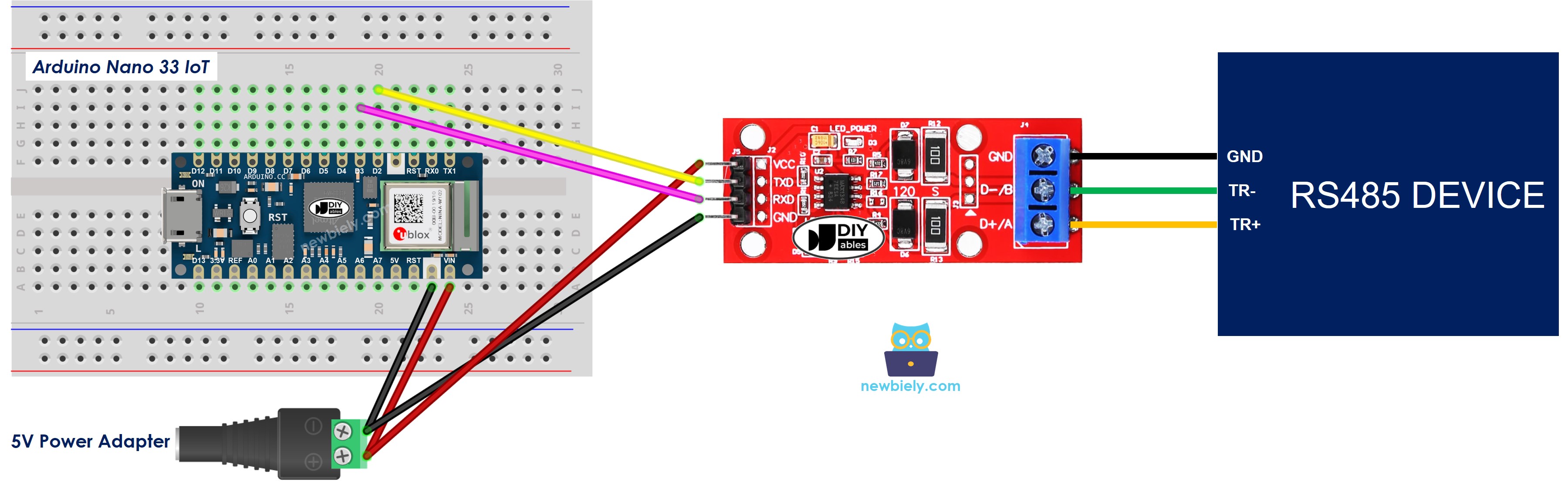
This image is created using Fritzing. Click to enlarge image
How To Program Arduino Nano 33 IoT to use the RS485 module
- Set up the pins for serial communication:
- Sets up the Serial connection:
- To read data from RS485, you can use these functions:
- Serial.read() (see https://arduinogetstarted.com/reference/serial-read)
- Serial.readBytes() (see https://arduinogetstarted.com/reference/serial-readbytes)
- Serial.readBytesUntil() (see https://arduinogetstarted.com/reference/serial-readbytesuntil)
- Serial.readString() (see https://arduinogetstarted.com/reference/serial-readstring)
- Serial.readStringUntil() (see https://arduinogetstarted.com/reference/serial-readstringuntil)
- To write data to RS485, you can use these functions:
- Serial.print() (see https://arduinogetstarted.com/reference/serial-print)
- Serial.println() (see https://arduinogetstarted.com/reference/serial-println)
- Serial.write() (see https://arduinogetstarted.com/reference/serial-write)
- You can also find more RS485 functions in the Serial reference at https://arduinogetstarted.com/reference/arduino-serial
Arduino Nano 33 IoT Code
Testing
You can try a test by sending information from your computer to the Arduino Nano 33 IoT using RS-485 and then back again. Follow these steps:
- Connect the Arduino Nano 33 IoT to your computer using an RS485-to-USB cable as shown below.
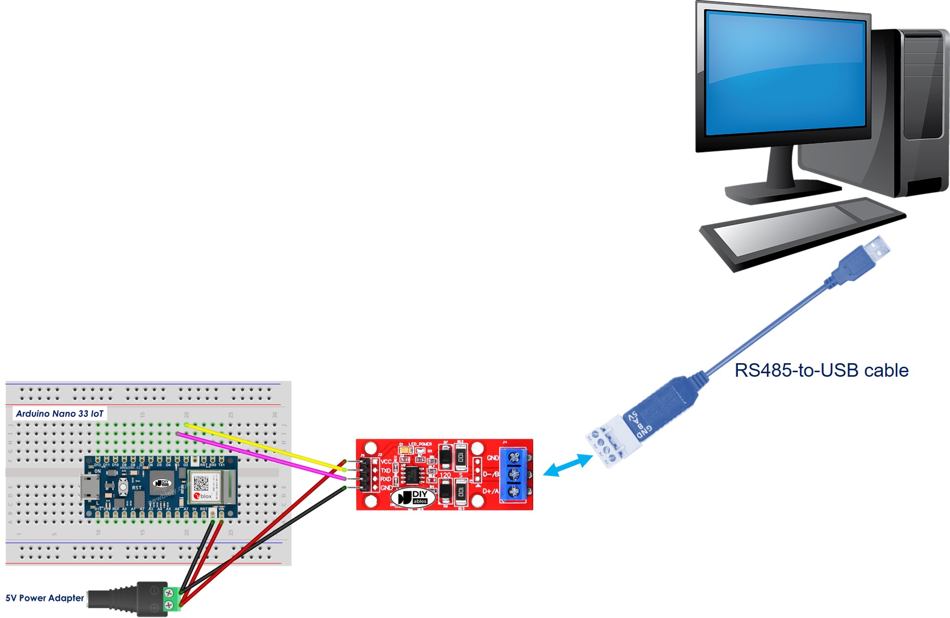
- Download and install a serial terminal program such as Tera Term or PuTTY.
- Open the terminal program and set up the serial connection details (like COM port and baud rate).
- Type some text in the terminal to send it to the Arduino Nano 33 IoT.
- If it works, you will see the same text appear back on the terminal.