Arduino Nano 33 IoT - Relay
You can plug an LED directly into the Arduino Nano 33 IoT, but you cannot plug high voltage devices like electric lights, pumps, electromagnetic locks, linear actuators, or large machines directly into it. Instead, you need a relay between the Arduino Nano 33 IoT and the high voltage devices. Without the relay, the high voltage may damage the Arduino Nano 33 IoT.
- Both controlling an LED and an electric lamp use the same Arduino Nano 33 IoT code. The code sets the board’s output pin to HIGH (on) or LOW (off) to switch them.
- Difference between controlling an LED and an electric lamp:
- Controlling an LED: An LED works with 3.3V or less, so you can connect it directly to the Arduino Nano 33 IoT’s pin.
- Controlling an electric lamp: An electric lamp usually works with a higher voltage (like 12V) and cannot be connected directly to the Arduino Nano 33 IoT’s pin. You need to use a relay between the Arduino pin and the electric lamp; otherwise, the Arduino could be damaged.
- Be very careful when working with high voltage. It can give you a shock or even kill you. If you're not completely sure what you're doing, don't touch anything. Instead, ask someone who really knows.
- Some relays can use both DC and AC voltage, but we strongly suggest you do not use AC voltage. Only use a DC device that is 24V or less.
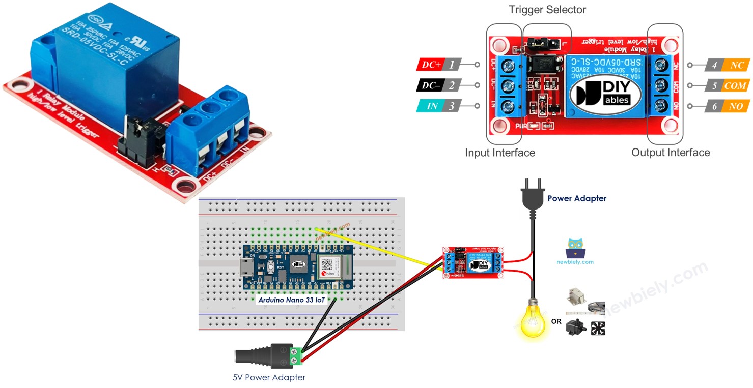
- The board has two sets of pins: input and output.
- Input pins (connect to the Arduino Nano 33 IoT):
- DC- pin: Connect to ground (GND or 0V)
- DC+ pin: Connect to power (VCC at 5V)
- IN pin: Receives the control signal from the Arduino Nano 33 IoT
- Output pins (connect to a high-voltage device, usually using a screw terminal):
- NO pin: Normally Open
- NC pin: Normally Closed
- COM pin: Common
- Normally open mode: Use only the COM pin and the NO pin.
- Normally closed mode: Use only the COM pin and the NC pin.
- Trigger mode that activates when the signal is low
- Trigger mode that activates when the signal is high
- Open by default mode
- Closed by default mode. These two options work in completely opposite ways.
- The normal open and normal closed modes work in opposite ways.
- Most relay modules support both normal open and normal closed modes.
- The low level trigger and high level trigger modes work in opposite ways.
- Not all relay modules support both low level trigger and high level trigger modes.
- A relay module can only use one mode at a time: either low level trigger or high level trigger.
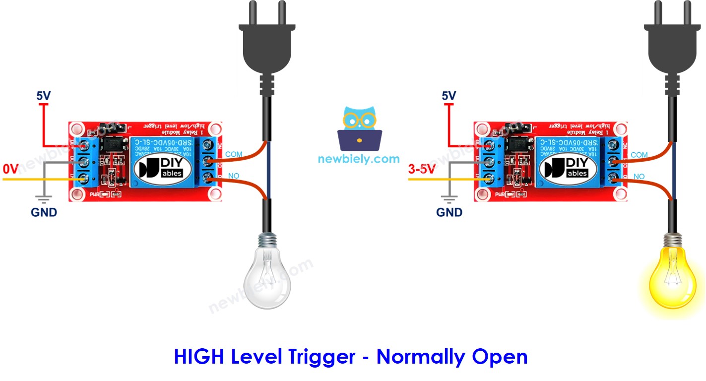
- When the IN pin is at LOW (0V), the switch is open and the device is turned off.
- When the IN pin is at HIGH (5V or 3.3V), the switch is closed and the device is turned on.
- If the IN pin is set to 0V, the switch closes and turns the device on. If the IN pin is set to 5V or 3.3V, the switch opens and turns the device off.
- Connect a pin from your Arduino Nano 33 IoT board to the relay's IN pin. Control the relay by changing the pin's setting to LOW or HIGH.
- When you power the Arduino Nano 33 IoT board using its USB port.
- When supplying power to the Arduino Nano 33 IoT board using the Vin pin.
- Set one of the Arduino Nano 33 IoT pins to work as an output by using the pinMode() function. For example, you can set pin D2 as the output pin.
- Use the digitalWrite() function to set the output pin to LOW (0 volts).
- Set the output pin to HIGH (3.3V) using the digitalWrite() function:
- Connect the components to the Arduino Nano 33 IoT board as depicted in the diagram.
- Use a USB cable to connect the Arduino Nano 33 IoT board to your computer.
- Launch the Arduino IDE on your computer.
- Select the Arduino Nano 33 IoT board and choose its corresponding COM port.
- Copy the code above and paste it into the Arduino program.
- Click the Upload button in the Arduino program to compile and send your code to the Arduino Nano 33 IoT board.
- Watch the LED strip blink.
Hardware Preparation
Or you can buy the following kits:
| 1 | × | DIYables Sensor Kit (18 sensors/displays) |
Additionally, some of these links are for products from our own brand, DIYables .
Overview of Relay
A relay is a smart switch that can turn electrical devices on or off. You can use the Arduino Nano 33 IoT to control the relay, which then controls high voltage devices.
WARNING
Safety first! Safety first!
Relay Pinout
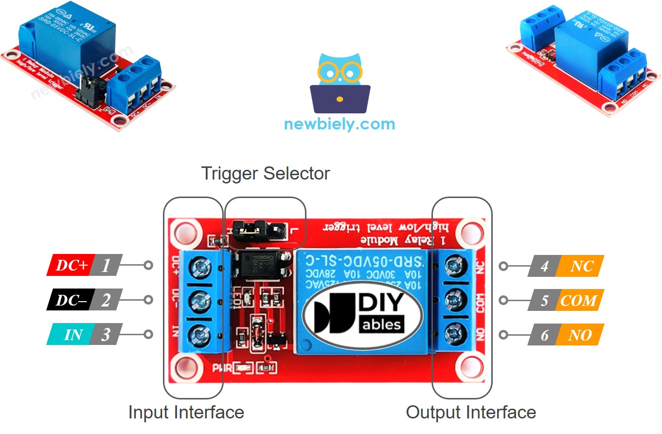
The relay pins are divided into two types: one type is for low voltage input and the other is for high voltage output.
Usually, we don't use all the high voltage pins. We typically use only two, depending on the mode we choose.
Also, if the relay works with both low and high level triggers, there is usually a jumper that lets you choose one of them.
※ NOTE THAT:
The order of the relay's pins might change depending on the manufacturer. Please check the labels on the relay carefully!
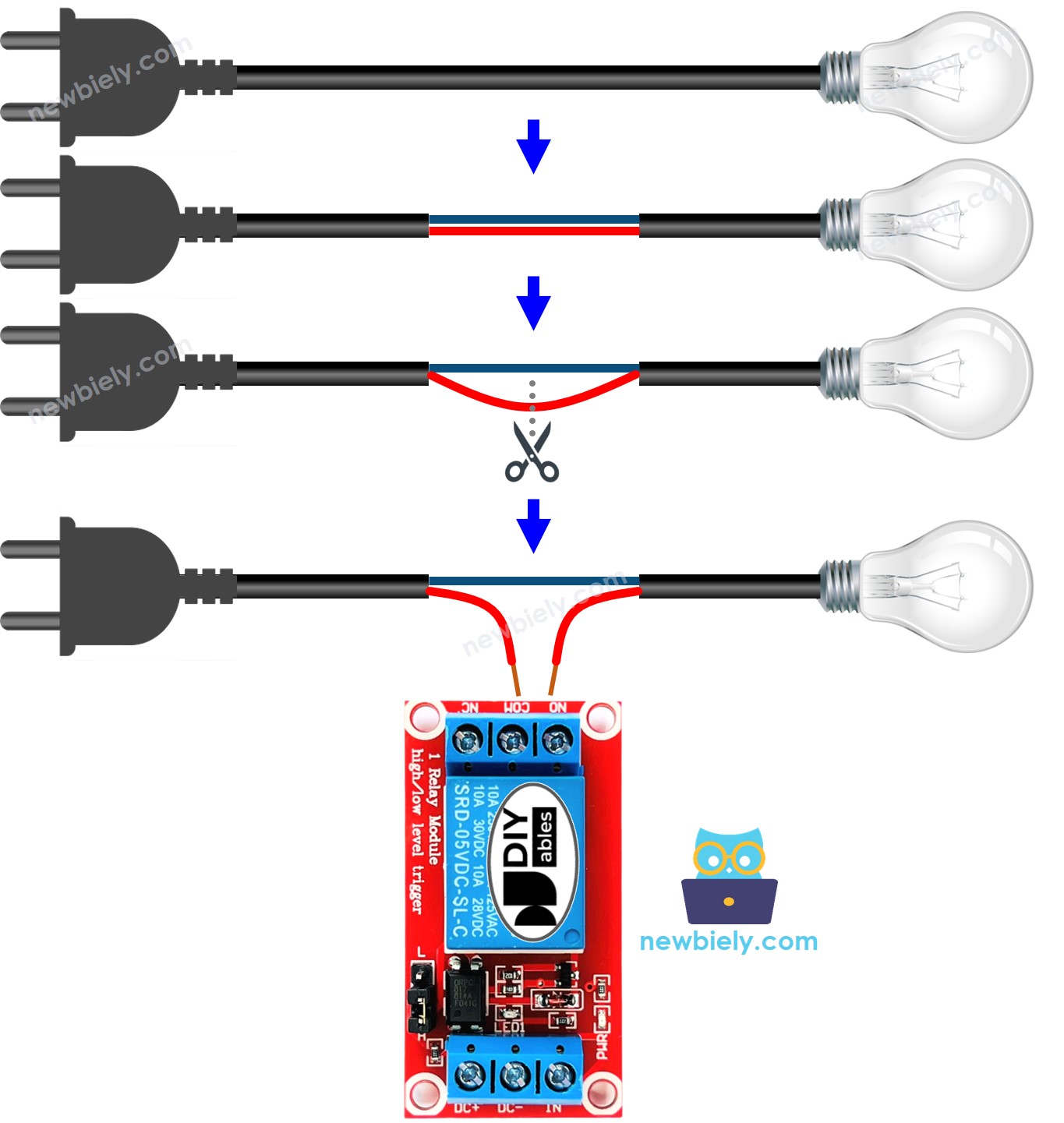
How to Connect the high-voltage Device to Relay
How Relay Works
A relay module can work in different ways, depending on the options we choose.
On the input side, you can choose one of the two opposite input modes below:
For output, you can choose one of the two opposite modes listed below:
Normally means that the IN pin is connected to a low level (0 volts).
Before we get into the details, let's quickly review some basic information.
Combining input modes and output modes gives you many ways to use it. If you're just starting out, we suggest using HIGH level trigger mode and normally open mode.
Because the LOW level trigger and HIGH level trigger modes work in opposite directions, we will explain the HIGH level trigger mode in detail next. The LOW level trigger mode works the other way.
HIGH Level Trigger - Normally Open Mode
Connect the high-power device to the COM pin and the NO pin. It works just like a switch:
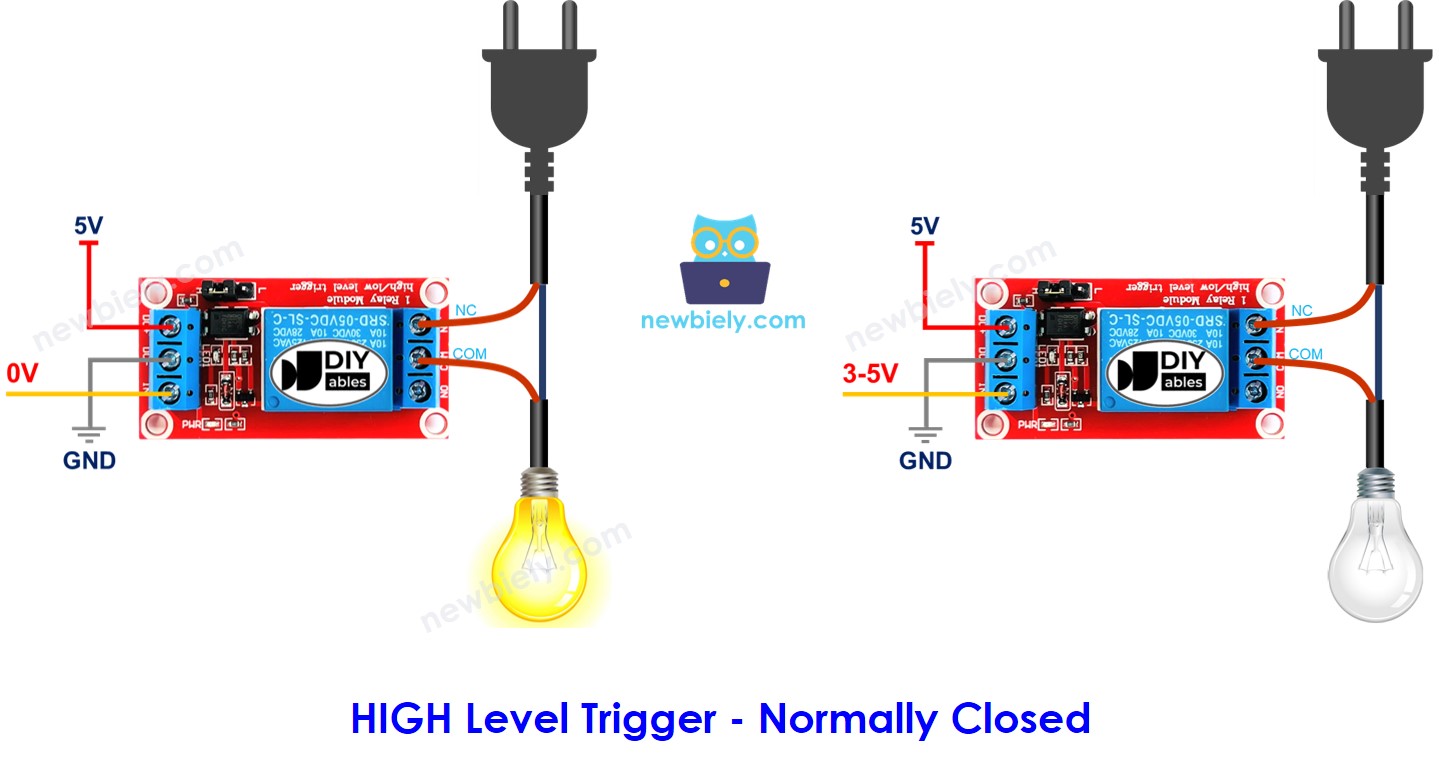
HIGH Level Trigger - Normally Closed Mode
Connect the high-voltage device to the COM pin and the NC pin, just like you would with a switch.
What option should we choose?
It depends on what you use it for.
Normally Open Mode vs Normally Closed Mode
The relay works like a switch. The table below explains the difference between the two modes in HIGH Level Trigger.
| Pins used | IN pin | Relay state | Device state | |
|---|---|---|---|---|
| Normally Open Mode | COM and NO pin | LOW | ⇒ open | ⇒ OFF |
| Normally Closed Mode | COM and NC pin | LOW | ⇒ closed | ⇒ ON |
| Normally Open Mode | COM and NO pin | HIGH | ⇒ closed | ⇒ ON |
| Normally Closed Mode | COM and NC pin | HIGH | ⇒ open | ⇒ OFF |
Arduino Nano 33 IoT - Relay
The Arduino Nano 33 IoT can control a high voltage device using a relay.
Controlling a relay is very simple. All we need is:
Wiring Diagram
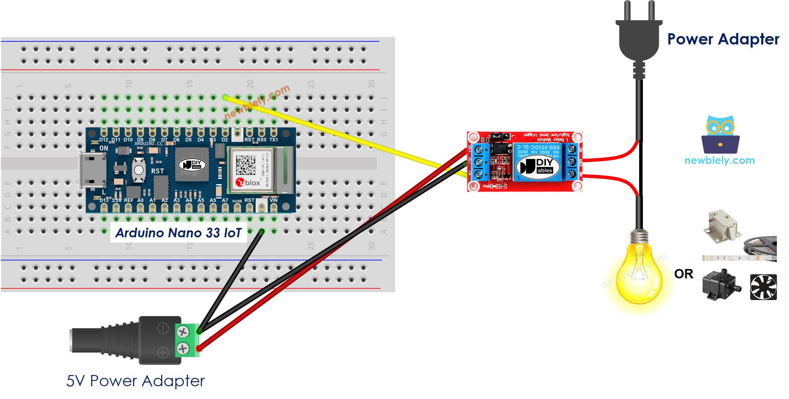
This image is created using Fritzing. Click to enlarge image
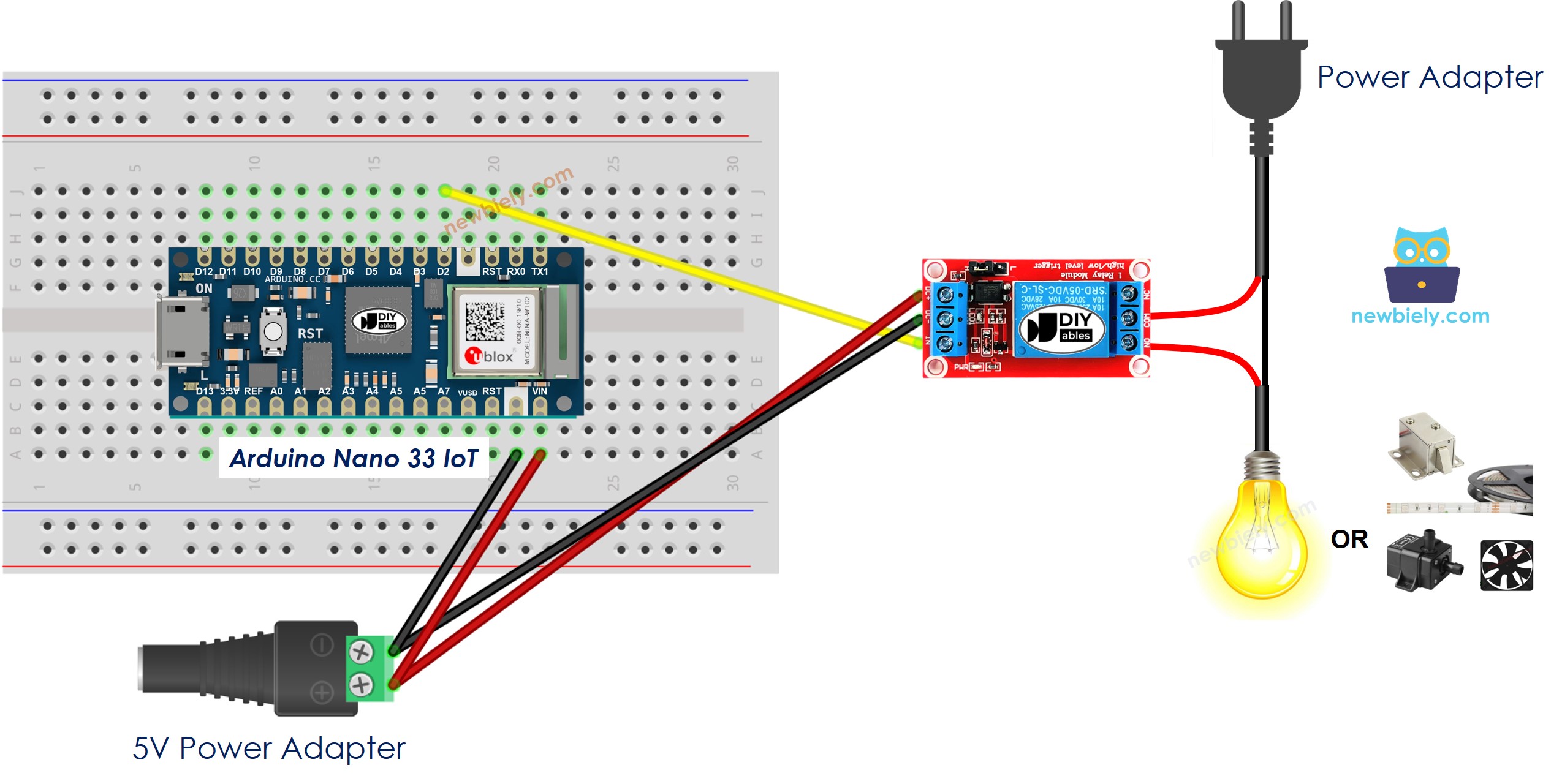
This image is created using Fritzing. Click to enlarge image
How To Program Relay using Arduino Nano 33 IoT
Arduino Nano 33 IoT Code
Detailed Instructions
If you are new to the Arduino Nano 33 IoT, be sure to check out our Getting Started with Arduino Nano 33 IoT tutorial. Then, follow these steps: