Arduino Nano 33 IoT - Potentiometer LED

This guide shows you how to use the Arduino Nano 33 IoT and a potentiometer to change the brightness of an LED.

Hardware Preparation

1×Arduino Nano 33 IoT
1×Micro USB Cable
1×Potentiometer
1×Alternatively, Potentiometer Kit
1×Alternatively, Potentiometer Module with Knob
1×LED Kit with resistor
1×LED (red)
1×220 ohm resistor
1×Breadboard
1×Jumper Wires
1×Optionally, DC Power Jack
1×Recommended: Screw Terminal Expansion Board for Arduino Nano
1×Recommended: Breakout Expansion Board for Arduino Nano
1×Recommended: Power Splitter for Arduino Nano

Or you can buy the following sensor kits:

1×DIYables Sensor Kit (30 sensors/displays)
1×DIYables Sensor Kit (18 sensors/displays)
Disclosure: Some of the links provided in this section are Amazon affiliate links. We may receive a commission for any purchases made through these links at no additional cost to you.
Additionally, some of these links are for products from our own brand, DIYables .

Overview of LED and Potentiometer

If you're new to using the LED, Potentiometer, and Arduino Nano 33 IoT, please check out these tutorials:

These tutorials explain how LED and Potentiometer work, their pinouts, how to connect them to the Arduino Nano 33 IoT, and how to program Arduino Nano 33 IoT to work with the LED and Potentiometer.

Wiring Diagram

The wiring diagram between Arduino Nano and 33 IoT Rotary Potentiometer LED

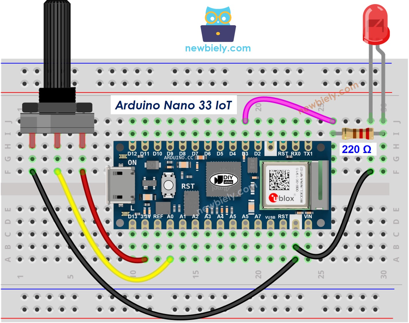
This image is created using Fritzing. Click to enlarge image

※ NOTE THAT:

Please note that the Arduino Nano 33 IoT pins A4 and A5 have built-in pull-up resistors for I2C communication. This can affect analog readings, so it is recommended to avoid using these pins with any devices/sensors that relies on ADC.

How To Program

  • Reads the value from an analog pin (a number between 0 and 4095)
int analogValue = analogRead(A0); // Retrieve the analog input from pin A0
  • Converts the brightness into a number between 0 and 255.
int brightness = map(analogValue, 0, 4095, 0, 255);
  • Changes the LED's brightness.
analogWrite(LED_PIN, brightness);

Arduino Nano 33 IoT Code

/* * This Arduino Nano 33 IoT code was developed by newbiely.com * * This Arduino Nano 33 IoT code is made available for public use without any restriction * * For comprehensive instructions and wiring diagrams, please visit: * https://newbiely.com/tutorials/arduino-nano-iot/arduino-nano-33-iot-potentiometer-led */ #define POTENTIOMETER_PIN A0 // The Arduino Nano 33 IoT pin connected to Potentiometer pin #define LED_PIN 3 // The Arduino Nano 33 IoT pin connected to LED's pin // the setup routine runs once when you press reset: void setup() { // initialize serial communication at 9600 bits per second: Serial.begin(9600); // declare LED pin to be an output: pinMode(LED_PIN, OUTPUT); } // the loop routine runs over and over again forever: void loop() { // reads the input on analog pin A0 (value between 0 and 4095) int analogValue = analogRead(POTENTIOMETER_PIN); // scales it to brightness (value between 0 and 255) int brightness = map(analogValue, 0, 4095, 0, 255); // sets the brightness LED that connects to pin 3 analogWrite(LED_PIN, brightness); // print out the value Serial.print("Analog value = "); Serial.print(analogValue); Serial.print(" => brightness = "); Serial.println(brightness); delay(100); }

Detailed Instructions

If you are new to the Arduino Nano 33 IoT, be sure to check out our Getting Started with Arduino Nano 33 IoT tutorial. Then, follow these steps:

  • Connect the components to the Arduino Nano 33 IoT board as depicted in the diagram.
  • Use a USB cable to connect the Arduino Nano 33 IoT board to your computer.
  • Launch the Arduino IDE on your computer.
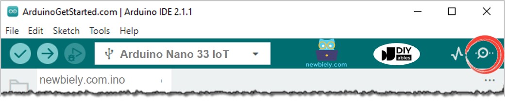
  • Select the Arduino Nano 33 IoT board and choose its corresponding COM port.
  • Copy the code above and paste it into the Arduino IDE.
  • Click the Upload button in Arduino IDE to compile and send the code to the Arduino Nano 33 IoT board.
  • Open the Serial Monitor in Arduino IDE.
How to open serial monitor on Arduino IDE
  • Turn the knob on the potentiometer.
  • Watch the LED become dim.
  • Look at the result on the Serial Monitor. It should look like this:
COM6
Send
Analog value = 6 => brightness = 1 Analog value = 34 => brightness = 8 Analog value = 89 => brightness = 22 Analog value = 149 => brightness = 37 Analog value = 214 => brightness = 53 Analog value = 297 => brightness = 74 Analog value = 365 => brightness = 90 Analog value = 431 => brightness = 107 Analog value = 510 => brightness = 127 Analog value = 589 => brightness = 146 Analog value = 695 => brightness = 173 Analog value = 790 => brightness = 196 Analog value = 970 => brightness = 241 Analog value = 996 => brightness = 248 Analog value = 1018 => brightness = 253 Analog value = 4095 => brightness = 255
Autoscroll Show timestamp
Clear output
9600 baud  
Newline  

Video Tutorial

※ OUR MESSAGES

  • As freelancers, We are AVAILABLE for HIRE. See how to outsource your project to us
  • Please feel free to share the link of this tutorial. However, Please do not use our content on any other websites. We invested a lot of effort and time to create the content, please respect our work!