Arduino Nano 33 IoT - DRV8825 Stepper Motor Driver
In this guide, we will look at the DRV8825 Stepper Motor Driver and learn how to use it with the Arduino Nano 33 IoT to control the stepper motor. We will explain:
- What is the DRV8825 module that drives stepper motors?
- How does the DRV8825 module work?
- How can you connect the DRV8825 driver with an Arduino Nano 33 IoT and a stepper motor?
- How do you write a simple program for the Arduino Nano 33 IoT to control a stepper motor using the DRV8825 driver?
Hardware Preparation
Or you can buy the following kits:
| 1 | × | DIYables Sensor Kit (18 sensors/displays) |
Additionally, some of these links are for products from our own brand, DIYables .
Overview of DRV8825 Stepper Motor Driver
The DRV8825 is a well-known module that controls bipolar stepper motors. You'll see it used in CNC machines, 3D printers, and robots. It lets you adjust the current, protects against getting too hot, and offers different stepping options, from full-steps to small 1/32 steps. It can handle up to 2.2A per motor coil with proper cooling and works with voltages between 8.2V and 45V, making it suitable for many stepper motors.
To learn about stepper motor basics like full-step, microstepping, unipolar stepper, and bipolar stepper, visit the Arduino Nano 33 IoT - Stepper Motor guide.
With only two pins on an Arduino Nano 33 IoT board, you can easily control how fast a NEMA 17 bipolar stepper motor moves and which way it turns.
DRV8825 Stepper Motor Driver Pinout
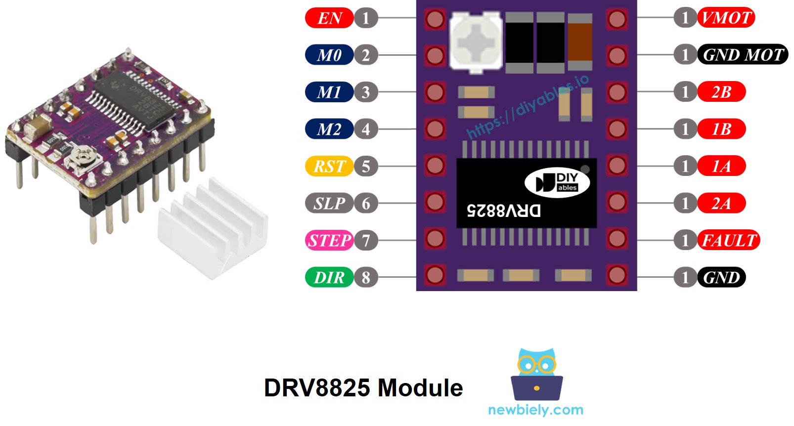
The DRV8825 Stepper Motor Driver has 16 pins. Here is a common pin layout for the DRV8825 board. Remember that some versions might use slightly different names for the pins, but their functions remain the same.
| Pin Name | Description |
|---|---|
| VMOT | Motor power supply (8.2 V to 45 V). This powers the stepper motor. |
| GND (for Motor) | Ground reference for the motor power supply. Connect this pin to the GND of the motor power supply |
| 2B, 2A | Outputs to Coil B of the stepper motor. |
| 1A, 1B | Outputs to Coil A of the stepper motor. |
| FAULT | Fault Detection Pin. This is an output pin that drives LOW whenever the H-bridge FETs are disabled as the result of over-current protection or thermal shutdown. |
| GND (for Logic) | Ground reference for the logic signals. Connect this pin to the GND of Arduino Nano 33 IoT |
| ENABLE | Active-Low pin to enable/disable the motor outputs. LOW = Enabled, HIGH = Disabled. |
| M1, M2, M3 | Microstepping resolution selector pins (see table below). |
| RESET | Active-Low reset pin - pulling this pin LOW resets the driver. |
| SLEEP | Active-Low sleep pin - pulling this pin LOW puts the driver into low-power sleep mode. |
| STEP | Step input - a rising edge on this pin advances the motor by one step (or one microstep, depending on microstepping setting). |
| DIR | Direction input - sets the rotation direction of the stepper motor. |
A small adjustable knob is included that allows you to set the current limit. This helps prevent the stepper motor and driver from overheating.
To sum up, these 16 pins are divided into groups based on what they do:
- Wires connected to the stepper motor: 1A, 1B, 2A, 2B.
- Wires connected to the Arduino Nano 33 IoT for controlling the driver: ENABLE, M1, M2, M3, RESET, SLEEP.
- Wires connected to the Arduino Nano 33 IoT for controlling motor direction and speed: DIR, STEP.
- Wire for sending error messages to the Arduino Nano 33 IoT: FAULT.
- Wires connected to the motor’s power source: VMOT, GND (motor power ground).
- Wire connected to the Arduino Nano 33 IoT’s ground: GND (logic ground).
The DRV8825 board does not need power from the Arduino Nano 33 IoT board for its logic because it gets power from the motor’s source through its own 3.3V voltage regulator. However, you must connect the Arduino Nano 33 IoT board's ground to the DRV8825 board's GND (logic) pin to ensure both share a common ground and work properly.
Microstep Configuration
The DRV8825 driver lets you divide each step into smaller parts, which is called microstepping. It works by sending different amounts of current to the motor coils.
For example, a NEMA 17 motor that moves 1.8 degrees at a time, taking 200 steps to go all the way around.
- Full-step mode: The motor moves 200 times for one complete turn.
- Half-step mode: The motor moves 400 times for one complete turn.
- Quarter-step mode: The motor moves 800 times for one complete turn.
- Eighth-step mode: The motor moves 1600 times for one complete turn.
- Sixteenth-step mode: The motor moves 3200 times for one complete turn.
- Thirty-second-step mode: The motor moves 6400 times for one complete turn.
When you increase the microstepping, the motor works more smoothly and accurately, but it needs more steps for a full rotation. If you keep the step pulse rate the same, each complete rotation will take longer, slowing down the motor.
If your microcontroller sends pulses quickly enough to match the higher number of steps, you can maintain or even increase the speed. The real limit is how fast both the driver and the microcontroller can process these pulses without skipping any steps.
DRV8825 Microstep Selection Pins
The DRV8825 has three input pins called M0, M1, and M2 for selecting the microstep resolution. By changing these pins to high or low signals, you can choose from six different microstepping resolutions.
| M0 Pin | M1 Pi | M2 Pi | Microstep Resolution |
|---|---|---|---|
| Low | Low | Low | Full step |
| High | Low | Low | Half step |
| Low | High | Low | 1/4 step |
| High | High | Low | 1/8 step |
| Low | Low | High | 1/16 step |
| High | Low | High | 1/32 step |
| Low | High | High | 1/32 step |
| High | High | High | 1/32 step |
These small pins for choosing steps have built-in resistors that keep them naturally set to a low state. If you do not connect them, the motor will operate in full-step mode.
How it Works
To use a stepper motor with the DRV8825 board, you need at least two pins from the Arduino Nano 33 IoT board. One pin is used for direction and another for steps. The DRV8825 board reads these signals from the Arduino to move the motor correctly.
- STEP Pin: Every pulse on this pin makes the motor move by one small step. Sometimes it makes a full step, based on the microstepping setup.
- DIR Pin: This pin determines the direction in which the motor rotates.
The driver takes these signals and its own settings to send commands to the motor through the 1A, 1B, 2A, and 2B pins.
You can also configure extra pins on the DRV8825 module (ENABLE, M1, M2, M3, RESET, SLEEP) using three different methods.
- Leave them unconnected so the driver uses its normal settings.
- Hook them directly to GND or VCC for a constant mode.
- Connect them to the Arduino Nano 33 IoT pins so you can control them with your code.
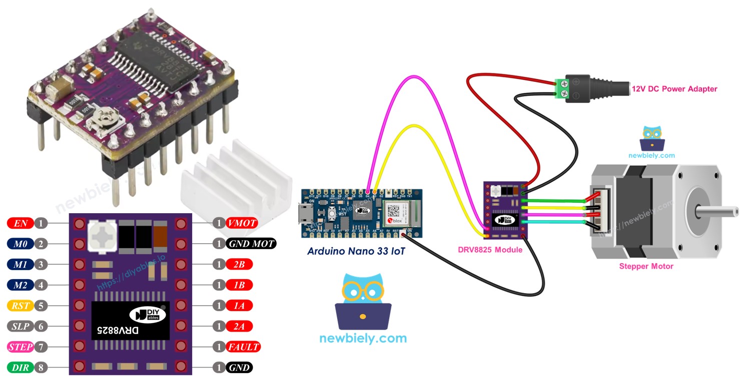
Wiring Diagram between Arduino Nano 33 IoT, DRV8825 module and Stepper Motor
The diagram below shows how to connect the Arduino Nano 33 IoT, the DRV8825 module, and the stepper motor. The DRV8825 driver works in its normal mode, called full-step.
This image is created using Fritzing. Click to enlarge image
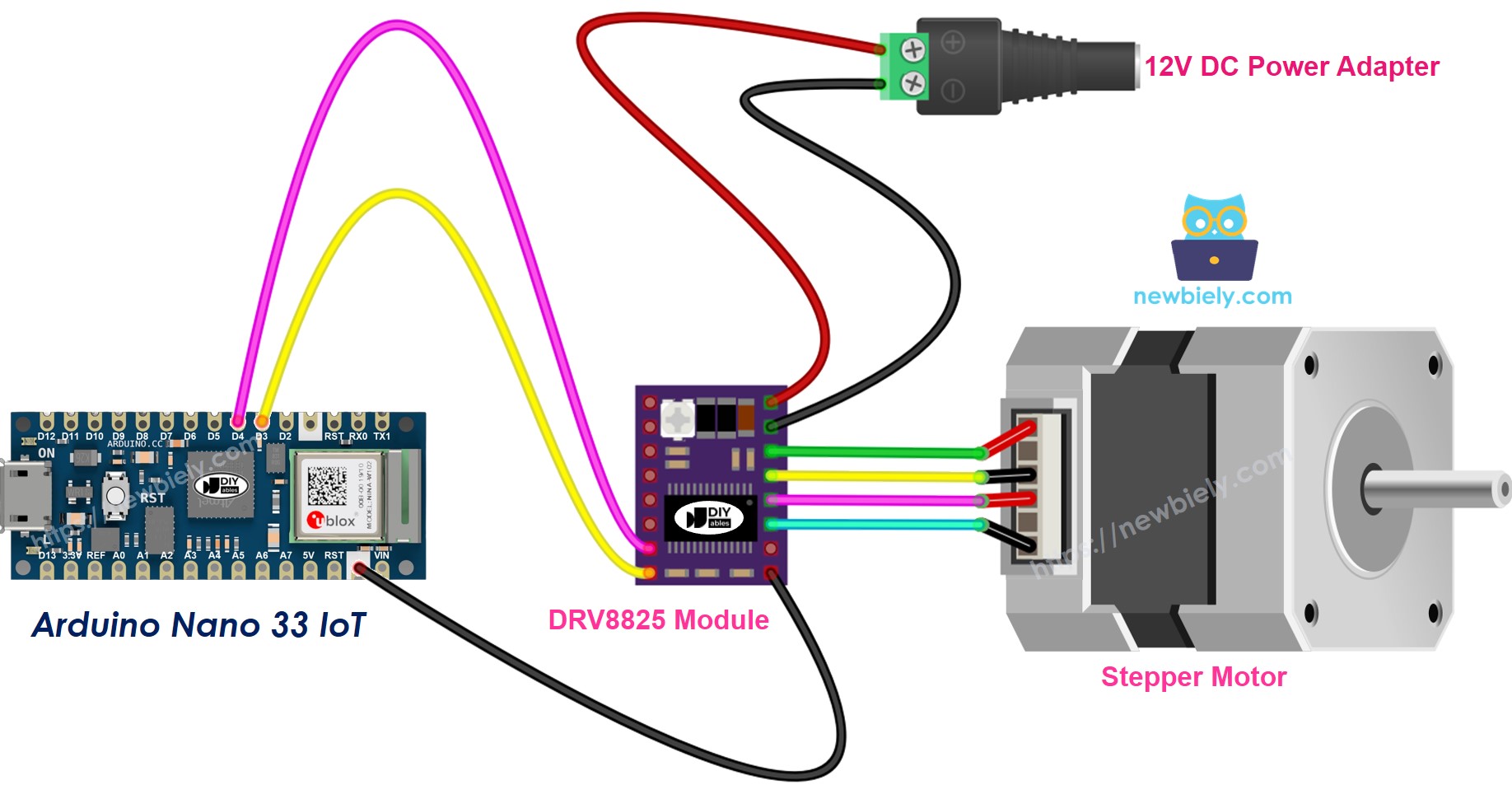
With all the details:
- VMOT: Connect this to the motor's power supply (for example, 12V).
- GND (for Motor): Connect this to the ground of the motor's power supply.
- 1A, 1B, 2A, 2B: Attach these to the stepper motor coils.
- STEP: Connect this to digital pin D4 on the Arduino Nano 33 IoT.
- DIR: Connect this to digital pin D3 on the Arduino Nano 33 IoT.
- GND (for Logic): Connect this to the Arduino Nano 33 IoT's ground pin.
- Other pins: Leave these not connected.
Arduino Nano 33 IoT Code
Detailed Instructions
If you are new to the Arduino Nano 33 IoT, be sure to check out our Getting Started with Arduino Nano 33 IoT tutorial. Then, follow these steps:
- Connect the components to the Arduino Nano 33 IoT board as depicted in the diagram.
- Use a USB cable to connect the Arduino Nano 33 IoT board to your computer.
- Launch the Arduino IDE on your computer.
- Select the Arduino Nano 33 IoT board and choose its corresponding COM port.
- Copy the code and open it in the Arduino IDE.
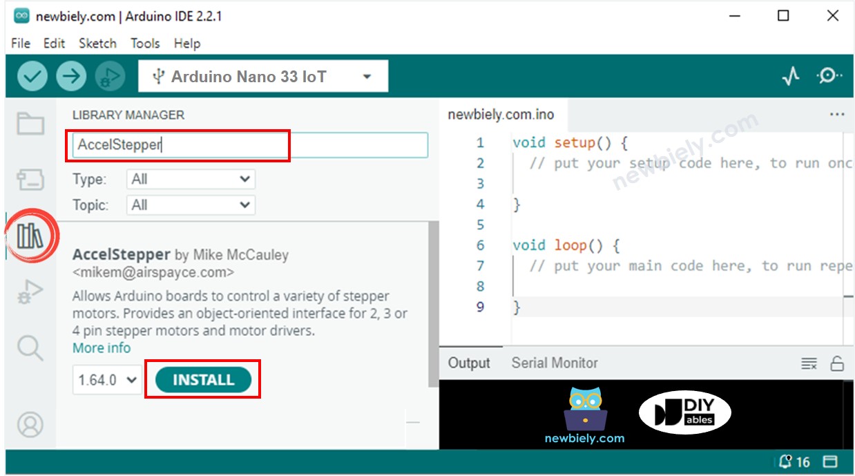
- Click on the Libraries icon on the left side of the Arduino IDE.
- Type AccelStepper in the search box, then find the AccelStepper library by Mike McCauley.
- Click the Install button to add the AccelStepper library.
- Copy the code and paste it into the Arduino IDE.
- Click the Upload button in the Arduino IDE to transfer the code to your Arduino Nano 33 IoT.
- You will see the motor turn back and forth.
When you use the motor in full-step mode, its movement might feel a bit rough, which is common. To make it move more smoothly, switch on microstepping by configuring the M1, M2, and M3 pins.