Arduino Nano 33 IoT - LED RGB
This guide shows you how to use the Arduino Nano 33 IoT to make an RGB LED glow in any color.
Hardware Preparation
Or you can buy the following kits:
| 1 | × | DIYables Sensor Kit (18 sensors/displays) |
Additionally, some of these links are for products from our own brand, DIYables .
Overview of RGB LED
The RGB LED can show many different colors by mixing red, green, and blue. It is made of three separate LEDs, one for each color, that are all in one case so it looks like a single LED.
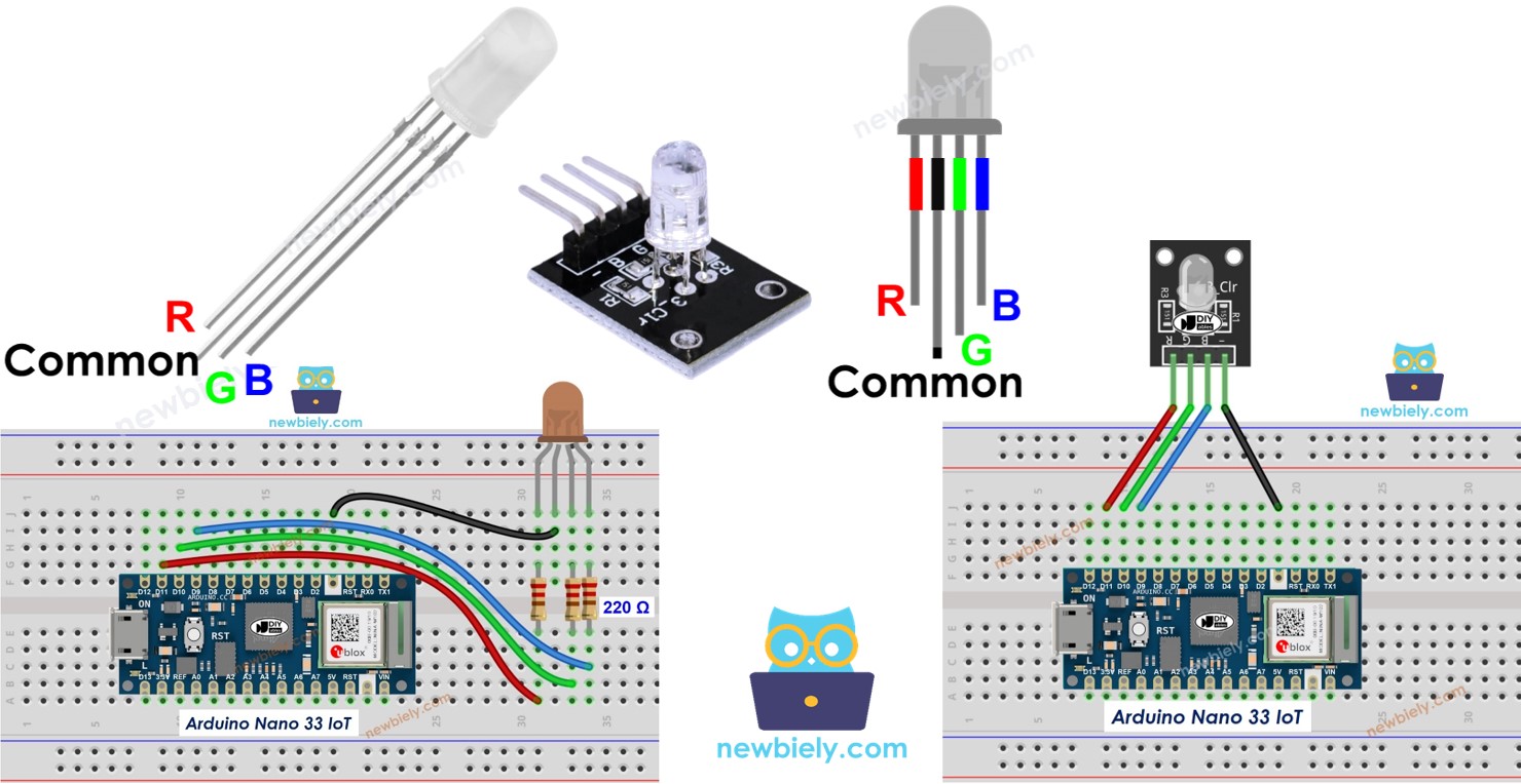
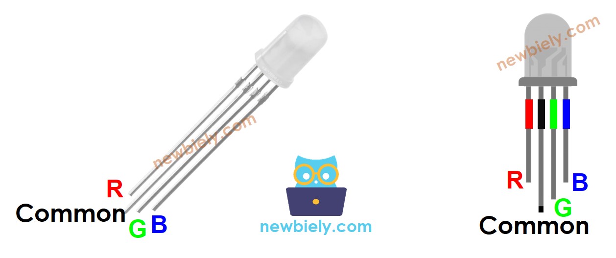
RGB LED Pinout
An RGB LED has four pins.
- R (red) pin: This pin controls the red light.
- G (green) pin: This pin controls the green light.
- B (blue) pin: This pin controls the blue light.
- Common (Cathode-) pin: Connect this pin to the ground (0V).
To connect an RGB LED to the Arduino Nano 33 IoT, you need to add resistors to limit the current. This step can make the wiring more difficult. Fortunately, you can use an RGB LED module that already has the resitors built in.
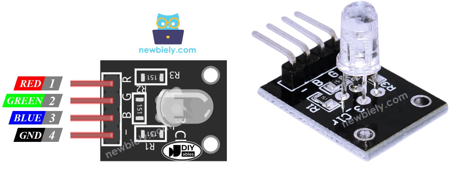
The RGB LED Module comes with four small connectors.
- Common (Cathode) pin: Connect this pin to ground (0 volts).
- R (red) pin: Use this pin to control the red light.
- G (green) pin: Use this pin to control the green light.
- B (blue) pin: Use this pin to control the blue light.
※ NOTE THAT:
There are two kinds of LED based on the shared pin: one is called common anode and the other is common cathode. This lesson uses a common cathode LED.
How RGB LED works
In physics, a color is made up of three main parts: red, green, and blue. Each part can have a value from 0 to 255. When you mix these values, you can create 256 x 256 x 256 different colors.
If we send PWM signals to the R, G, and B pins, the RGB LED shows a color based on the PWM duty cycle values. By changing the duty cycle of these PWM signals (from 0 to 255), the RGB LED can display any color. The color values of Red (R), Green (G), and Blue (B) match the PWM duty cycles on their respective R, G, and B pins.
Wiring Diagram between RGB LED and Arduino Nano 33 IoT
- Simple wiring diagram to connect the Arduino Nano 33 IoT with an RGB LED.
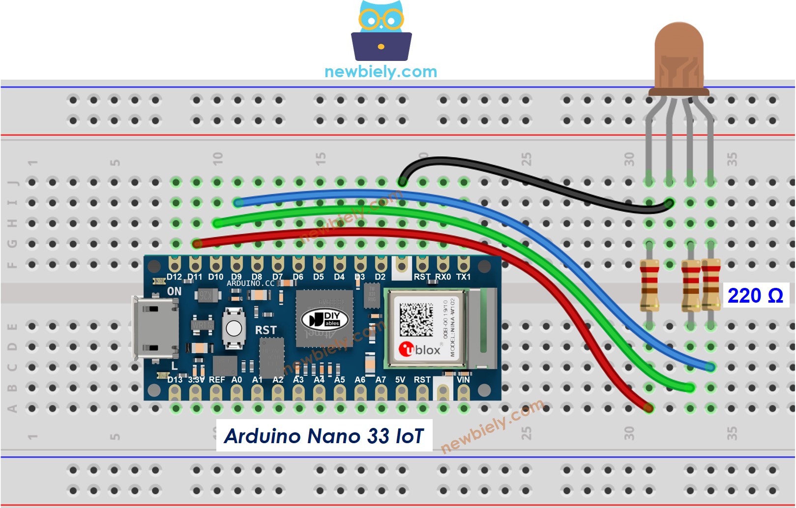
This image is created using Fritzing. Click to enlarge image
- Simple wiring plan for connecting the Arduino Nano 33 IoT to an RGB LED module.
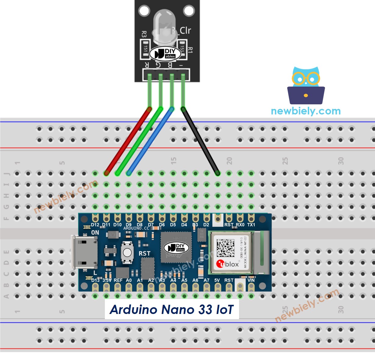
This image is created using Fritzing. Click to enlarge image
How To Control RGB LED
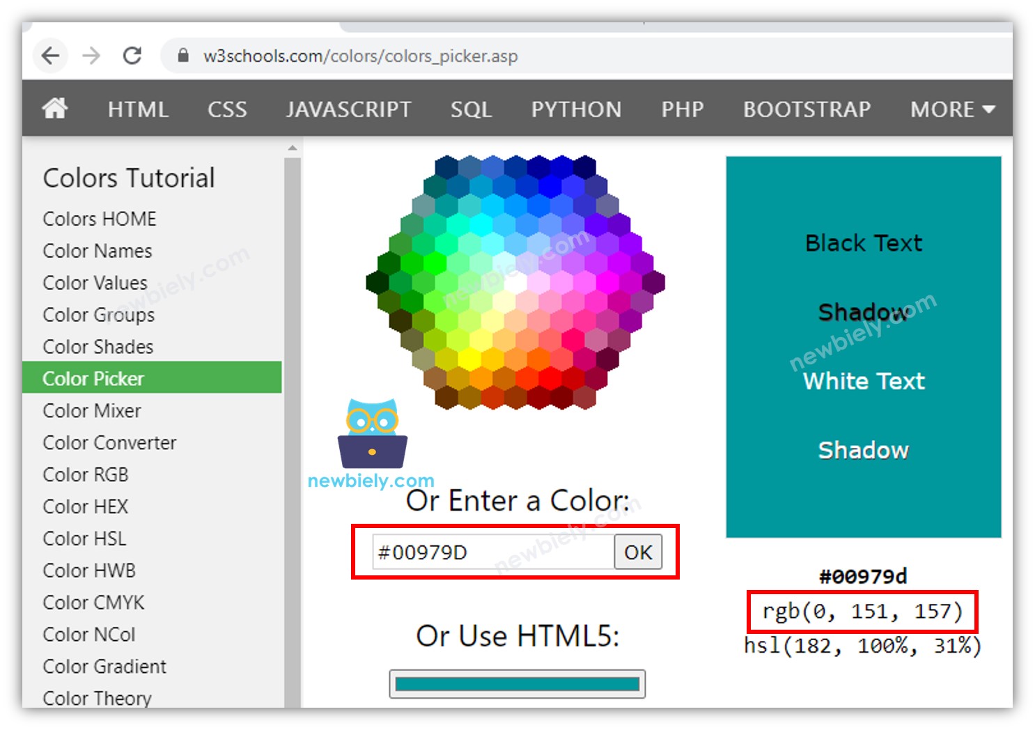
Imagine you want your RGB LED to show the color #00979D. You can do it using this step:
- Find a color code. Here are some hints:
- Use this color picker to choose any color you like: https://www.w3schools.com/colors/colors_picker.asp
- If you want to get a color from a picture, use this tool: https://html-color-codes.info/colors-from-image/
- Next, change the color code into R, G, B numbers with this tool: https://www.w3schools.com/colors/colors_hexadecimal.asp. For example, you might get R = 0, G = 151, B = 157.
- Choose which Arduino Nano 33 IoT pins will connect to the red, green, and blue pins. For example:
- Set these Arduino Nano 33 IoT pins to work as outputs.
- Make the LED glow with this color: #00979D (Red: 0, Green: 151, Blue: 157).
Arduino Nano 33 IoT - RGB LED Example Code
This code changes the LED color by cycling through these colors in order:
- Color Code #00C9CC – This color is made with red: 0, green: 201, blue: 204.
- Color Code #F7788A – This color is made with red: 247, green: 120, blue: 138.
- Color Code #34A853 – This color is made with red: 52, green: 168, blue: 83.