Arduino Nano 33 IoT - LED - Blink Without Delay

One of the first programs beginners try is to make an LED blink. The easiest way to blink an LED is to use the delay() function. This function stops the Arduino Nano 33 IoT from doing other tasks. This is fine if you just want to blink one LED. But if you want to blink more LEDs or do other things at the same time, you cannot use the delay() function. We need another solution. This guide will show you how to handle multiple tasks without using delay(). Specifically, we will learn how to blink an LED and check a button’s state.

We will go through three examples below and see how they differ.

This approach allows the Arduino Nano 33 IoT to handle many tasks at the same time. Turning an LED on and off is just one example.

Hardware Preparation

1×Arduino Nano 33 IoT
1×Micro USB Cable
1×LED Kit with resistor
1×LED (red)
1×220 ohm resistor
1×Breadboard-mount Button with Cap
1×Breadboard-mount Button Kit
1×Panel-mount Push Button
1×Push Button Module
1×Breadboard
1×Jumper Wires
1×Optionally, DC Power Jack
1×Recommended: Screw Terminal Expansion Board for Arduino Nano
1×Recommended: Breakout Expansion Board for Arduino Nano
1×Recommended: Power Splitter for Arduino Nano

Or you can buy the following sensor kits:

1×DIYables Sensor Kit (30 sensors/displays)
1×DIYables Sensor Kit (18 sensors/displays)
Disclosure: Some of the links provided in this section are Amazon affiliate links. We may receive a commission for any purchases made through these links at no additional cost to you.
Additionally, some of these links are for products from our own brand, DIYables .

Overview of LED and Button

If you're new to using the LED, Button, and Arduino Nano 33 IoT, please check out these tutorials:

These tutorials explain how LED and Button work, their pinouts, how to connect them to the Arduino Nano 33 IoT, and how to program Arduino Nano 33 IoT to work with the LED and Button.

Wiring Diagram

The wiring diagram between Arduino Nano and 33 IoT LED button

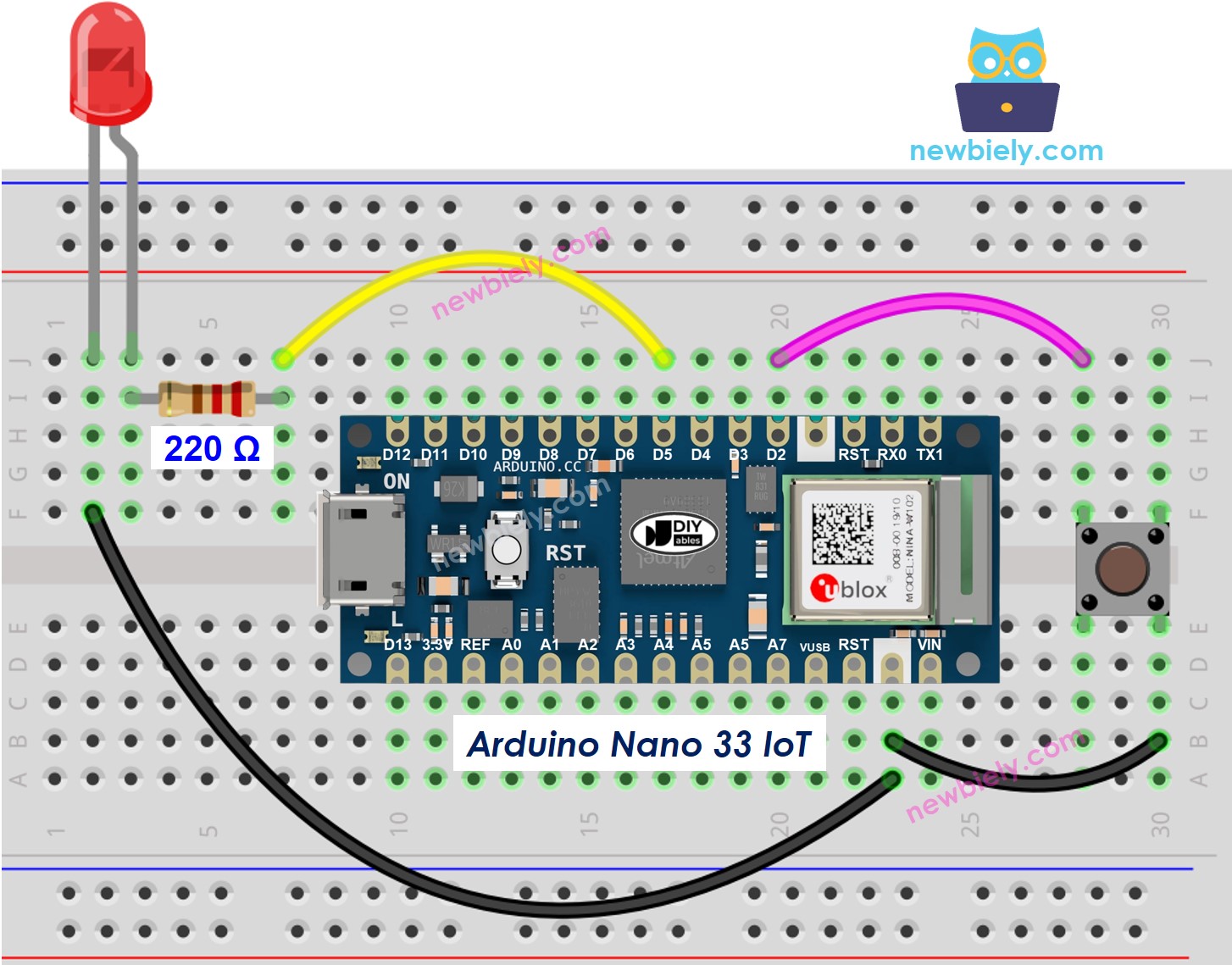
This image is created using Fritzing. Click to enlarge image

Let's compare two versions of the Arduino Nano 33 IoT code that makes an LED blink: one version uses the delay() function and the other version does not.

※ NOTE THAT:

Please note that the Arduino Nano 33 IoT pins A4 and A5 have built-in pull-up resistors for I2C communication. Although these pins can be used as digital input pins, it is recommended to avoid using them for digital input. If you must use them, do not use internal or external pull-down resistors for these pins

Arduino Nano 33 IoT Code - With Delay

/* * This Arduino Nano 33 IoT code was developed by newbiely.com * * This Arduino Nano 33 IoT code is made available for public use without any restriction * * For comprehensive instructions and wiring diagrams, please visit: * https://newbiely.com/tutorials/arduino-nano-iot/arduino-nano-33-iot-led-blink-without-delay */ #define LED_PIN 5 // The Arduino Nano 33 IoT pin D5 connected to LED #define BUTTON_PIN 2 // The Arduino Nano 33 IoT pin D2 connected to button #define BLINK_INTERVAL 1000 // interval at which to blink LED (milliseconds) int led_state = LOW; // led_state used to set the LED int prev_button_state = LOW; // will store last time button was updated void setup() { Serial.begin(9600); // set the digital pin as output: pinMode(LED_PIN, OUTPUT); // set the digital pin as an input: pinMode(BUTTON_PIN, INPUT_PULLUP); } void loop() { // if the LED is off turn it on and vice-versa: led_state = (led_state == LOW) ? HIGH : LOW; // set the LED with the led_state of the variable: digitalWrite(LED_PIN, led_state); delay(BLINK_INTERVAL); // If button is pressed during this time, Arduino CANNOT detect int button_state = digitalRead(BUTTON_PIN); if (button_state != prev_button_state) { // print out the state of the button: Serial.println(button_state); // save the last state of button prev_button_state = button_state; } // DO OTHER WORKS HERE }

Detailed Instructions

If you are new to the Arduino Nano 33 IoT, be sure to check out our Getting Started with Arduino Nano 33 IoT tutorial. Then, follow these steps:

  • Connect the components to the Arduino Nano 33 IoT board as depicted in the diagram.
  • Use a USB cable to connect the Arduino Nano 33 IoT board to your computer.
  • Launch the Arduino IDE on your computer.
  • Select the Arduino Nano 33 IoT board and choose its corresponding COM port.
  • Copy the code from above and paste it into the Arduino IDE.
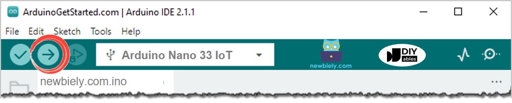
  • Click the Upload button in the Arduino IDE to compile the code and send it to the Arduino Nano 33 IoT board.
How to upload Arduino Nano 33 IoT code on Arduino IDE
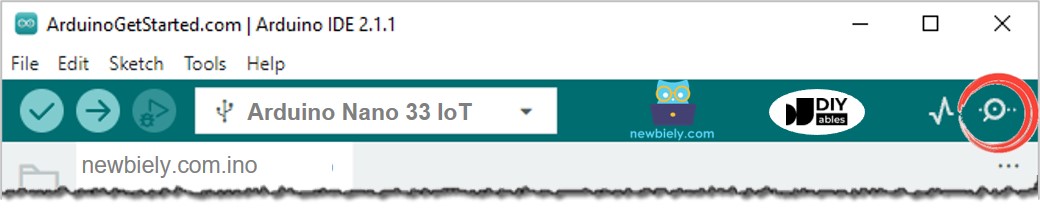
  • Open the Serial Monitor in the Arduino software.
How to open serial monitor on Arduino IDE
  • Press the button 4 times. Watch the LED as it changes between on and off every second. Look at the output in the Serial Monitor.
COM6
Send
1 0
Autoscroll Show timestamp
Clear output
9600 baud  
Newline  
  • On the Serial Monitor, you won't see the state change to 0 four times (after 4 presses). This happens because, during the delay period, the Arduino Nano 33 IoT cannot notice the change.

Arduino Nano 33 IoT Code - Without Delay

/* * This Arduino Nano 33 IoT code was developed by newbiely.com * * This Arduino Nano 33 IoT code is made available for public use without any restriction * * For comprehensive instructions and wiring diagrams, please visit: * https://newbiely.com/tutorials/arduino-nano-iot/arduino-nano-33-iot-led-blink-without-delay */ #define LED_PIN 5 // The Arduino Nano 33 IoT pin D5 connected to LED #define BUTTON_PIN 2 // The Arduino Nano 33 IoT pin D2 connected to button #define BLINK_INTERVAL 1000 // interval at which to blink LED (milliseconds) int led_state = LOW; // led_state used to set the LED int prev_button_state = LOW; // will store last time button was updated unsigned long prev_millis = 0; // will store last time LED was updated void setup() { Serial.begin(9600); // set the digital pin as output: pinMode(LED_PIN, OUTPUT); // set the digital pin as an input: pinMode(BUTTON_PIN, INPUT_PULLUP); } void loop() { // check to see if it's time to blink the LED; that is, if the difference // between the current time and last time you blinked the LED is bigger than // The interval at which you want to blink the LED. unsigned long current_millis = millis(); if (current_millis - prev_millis >= BLINK_INTERVAL) { // if the LED is off turn it on and vice-versa: led_state = (led_state == LOW) ? HIGH : LOW; // set the LED with the led_state of the variable: digitalWrite(LED_PIN, led_state); // save the last time you blinked the LED prev_millis = current_millis; } // check button state's change int button_state = digitalRead(BUTTON_PIN); if (button_state != prev_button_state) { // print out the state of the button: Serial.println(button_state); // save the last state of button prev_button_state = button_state; } // DO OTHER WORKS HERE }

Detailed Instructions

  • Run the code above and press the button 4 times.
  • Watch the LED light: It turns on and off every second.
  • Look at the results in the Serial Monitor.
COM6
Send
1 0 1 0 1 0 1 0
Autoscroll Show timestamp
Clear output
9600 baud  
Newline  
  • Every press was noticed.

Line-by-line Code Explanation

The Arduino Nano 33 IoT code above has an explanation for every line. Please check the comments in the code!

Adding More Tasks

This code makes two lights blink at different speeds and checks if the button is pressed.

/* * This Arduino Nano 33 IoT code was developed by newbiely.com * * This Arduino Nano 33 IoT code is made available for public use without any restriction * * For comprehensive instructions and wiring diagrams, please visit: * https://newbiely.com/tutorials/arduino-nano-iot/arduino-nano-33-iot-led-blink-without-delay */ #define LED_PIN_1 6 // The Arduino Nano 33 IoT pin D6 connected to LED 1 #define LED_PIN_2 5 // The Arduino Nano 33 IoT pin D5 connected to LED 2 #define BUTTON_PIN 2 // The Arduino Nano 33 IoT pin D2 connected to button #define BLINK_INTERVAL_1 1000 // interval at which to blink LED 1 (milliseconds) #define BLINK_INTERVAL_2 500 // interval at which to blink LED 2 (milliseconds) int led_state_1 = LOW; // led_state used to set the LED 1 int led_state_2 = LOW; // led_state used to set the LED 2 int prev_button_state = LOW; // will store last time button was updated unsigned long prev_millis_1 = 0; // will store last time LED 1 was updated unsigned long prev_millis_2 = 0; // will store last time LED 2 was updated void setup() { Serial.begin(9600); // set the digital pin as output: pinMode(LED_PIN_1, OUTPUT); pinMode(LED_PIN_2, OUTPUT); // set the digital pin as an input: pinMode(BUTTON_PIN, INPUT_PULLUP); } void loop() { unsigned long current_millis = millis(); // check to see if it's time to blink the LED 1 if (current_millis - prev_millis_1 >= BLINK_INTERVAL_1) { // if the LED is off turn it on and vice-versa: led_state_1 = (led_state_1 == LOW) ? HIGH : LOW; // set the LED with the led_state of the variable: digitalWrite(LED_PIN_1, led_state_1); // save the last time you blinked the LED prev_millis_1 = current_millis; } // check to see if it's time to blink the LED 2 if (current_millis - prev_millis_2 >= BLINK_INTERVAL_2) { // if the LED is off turn it on and vice-versa: led_state_2 = (led_state_2 == LOW) ? HIGH : LOW; // set the LED with the led_state of the variable: digitalWrite(LED_PIN_2, led_state_2); // save the last time you blinked the LED prev_millis_2 = current_millis; } // check button state's change int button_state = digitalRead(BUTTON_PIN); if (button_state != prev_button_state) { // print out the state of the button: Serial.println(button_state); // save the last state of button prev_button_state = button_state; } // DO OTHER WORKS HERE }

Video Tutorial

※ OUR MESSAGES

  • As freelancers, We are AVAILABLE for HIRE. See how to outsource your project to us
  • Please feel free to share the link of this tutorial. However, Please do not use our content on any other websites. We invested a lot of effort and time to create the content, please respect our work!