Arduino Nano 33 IoT - RFID
This guide shows you how to use the Arduino Nano 33 IoT with the RC522 RFID/NFC reader to get data from an RFID/NFC tag.
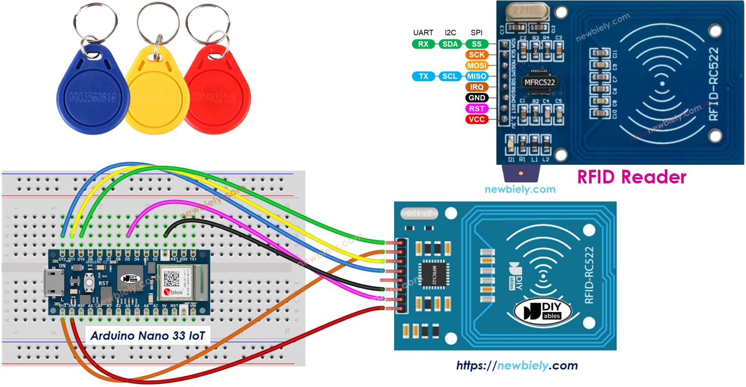
Hardware Preparation
Or you can buy the following kits:
| 1 | × | DIYables Sensor Kit (18 sensors/displays) |
Disclosure: Some of the links provided in this section are Amazon affiliate links. We may receive a commission for any purchases made through these links at no additional cost to you.
Additionally, some of these links are for products from our own brand, DIYables .
Additionally, some of these links are for products from our own brand, DIYables .
Overview of RFID-RC522 Module
Pinout
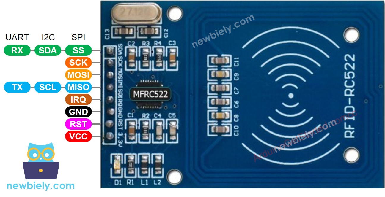
The RFID-RC522 module has 8 pins. Some pins work for three different communication types: SPI, I2C, and UART. One mode can be used at a time. The pins are:
- GND pin: Connect this pin to ground (0V).
- VCC pin: Connect this pin to the power supply (3.3V).
- RST pin: This pin is used to reset or turn off the device. When the pin is low, the device powers off. When it goes high, the device resets.
- IRQ pin: This pin sends an alert to the Arduino Nano 33 IoT when an RFID tag comes near.
- MISO/SCL/TX pin: This pin acts as:
- MISO if the SPI connection is used.
- SCL if the I2C connection is used.
- TX if the UART connection is used.
- MOSI pin: This pin works as MOSI when using the SPI connection.
- SCK pin: This pin works as SCK with the SPI connection.
- SS/SDA/RX pin: This pin works as:
- SS when the SPI connection is used.
- SDA when using the I2C connection.
- RX when using the UART connection.
- The order of the pins may be different depending on the manufacturer. Always follow the labels printed on the module. The image above shows the pin layout for modules made by DIYables.
- The RFID-RC522 module runs on 3.3V. Do not connect its VCC pin to 5V because 5V can damage the module.
- This guide uses the SPI interface for communication between the Arduino Nano 33 IoT and the RFID-RC522 module.
※ NOTE THAT:
Wiring Diagram
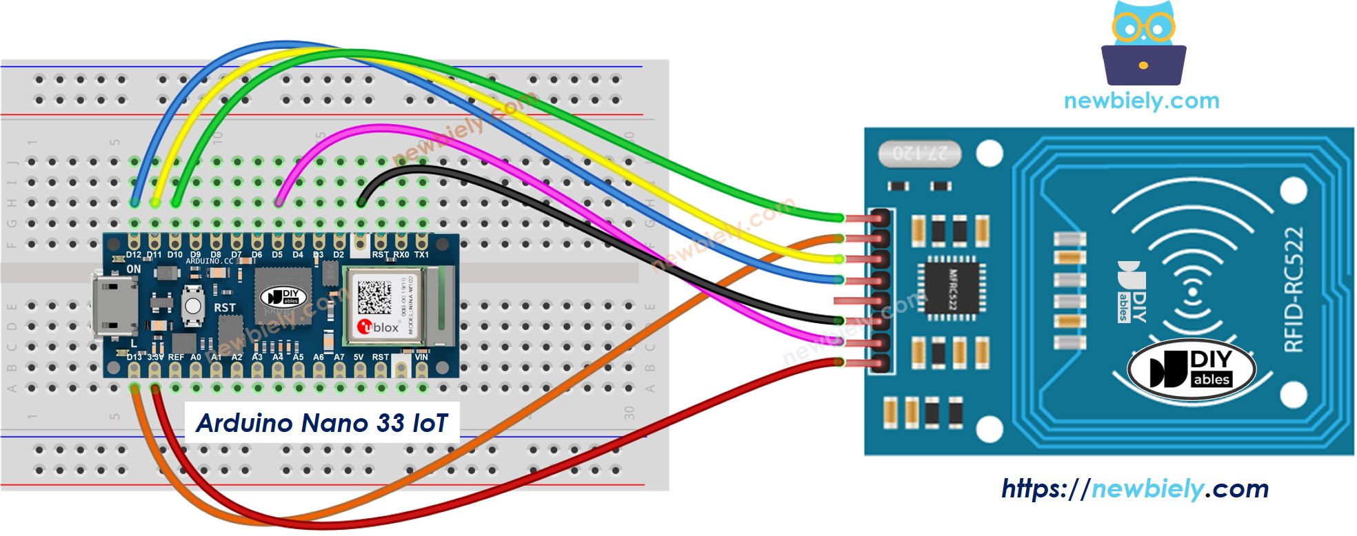
This image is created using Fritzing. Click to enlarge image
The wiring table between RFID/NFC RC522 Module and Arduino Nano 33 IoT
| RFID/NFC RC522 | Arduino Nano 33 IoT |
|---|---|
| SS | → D10 |
| SCK | → D13 |
| MOSI | → D11 |
| MISO | → D12 |
| IRQ | not connected |
| GND | → GND |
| RST | → D5 |
| VCC | → 3.3V |
Arduino Nano 33 IoT RFID/NFC Code
/*
* This Arduino Nano 33 IoT code was developed by newbiely.com
*
* This Arduino Nano 33 IoT code is made available for public use without any restriction
*
* For comprehensive instructions and wiring diagrams, please visit:
* https://newbiely.com/tutorials/arduino-nano-iot/arduino-nano-33-iot-rfid
*/
#include <SPI.h>
#include <MFRC522.h>
#define SS_PIN 10 // Arduino Nano 33 IoT pin connected to RC522's SS pin
#define RST_PIN 5 // Arduino Nano 33 IoT pin connected to RC522's RST pin
MFRC522 rfid(SS_PIN, RST_PIN);
void setup() {
Serial.begin(9600);
SPI.begin(); // init SPI bus
rfid.PCD_Init(); // init MFRC522
Serial.println("Tap an RFID/NFC tag on the RFID-RC522 reader");
}
void loop() {
if (rfid.PICC_IsNewCardPresent()) { // new tag is available
if (rfid.PICC_ReadCardSerial()) { // NUID has been readed
MFRC522::PICC_Type piccType = rfid.PICC_GetType(rfid.uid.sak);
Serial.print("RFID/NFC Tag Type: ");
Serial.println(rfid.PICC_GetTypeName(piccType));
// print UID in Serial Monitor in the hex format
Serial.print("UID:");
for (int i = 0; i < rfid.uid.size; i++) {
Serial.print(rfid.uid.uidByte[i] < 0x10 ? " 0" : " ");
Serial.print(rfid.uid.uidByte[i], HEX);
}
Serial.println();
rfid.PICC_HaltA(); // halt PICC
rfid.PCD_StopCrypto1(); // stop encryption on PCD
}
}
}
Detailed Instructions
If you are new to the Arduino Nano 33 IoT, be sure to check out our Getting Started with Arduino Nano 33 IoT tutorial. Then, follow these steps:
- Connect the components to the Arduino Nano 33 IoT board as depicted in the diagram.
- Use a USB cable to connect the Arduino Nano 33 IoT board to your computer.
- Launch the Arduino IDE on your computer.
- Select the Arduino Nano 33 IoT board and choose its corresponding COM port.
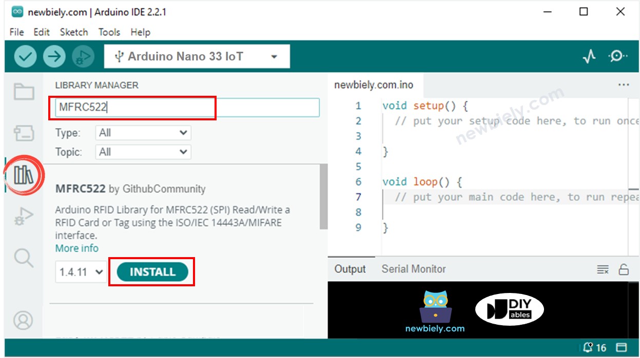
- Click the Library Manager icon on the left side of the Arduino IDE screen.
- Type MFRC522 in the search box and look for the library from GithubCommunity.
- Click the Install button to add the library.
- Copy the code above and paste it into the Arduino program.
- Click the Upload button to check and send the code to your Arduino Nano 33 IoT board.
- Open the Serial Monitor in the Arduino program to see the output.
- Touch a few RFID or NFC tags on the RFID-RC522 module. Then, look at the Serial Monitor to see the unique tag ID.
8
Serial.println("Hello World!");
Message (Enter to send message to 'Arduino Nano 33 IoT' on 'COM15')
New Line
9600 baud
Tap an RFID/NFC tag on the RFID-RC522 reader
RFID/NFC tag Type: MIFARE 1KB
UID: 2B B8 59 B1
RFID/NFC tag Type: MIFARE Ultralight or Ultralight C
UID: 15 75 46 7A 2C 5B 7E