Arduino Nano 33 IoT - Control Pump
This guide shows you how to use the Arduino Nano 33 IoT board to control a pump. You can also use this guide to create your own aquarium, cocktail maker, coffee machine, or watering system.
Hardware Preparation
Or you can buy the following kits:
| 1 | × | DIYables Sensor Kit (18 sensors/displays) |
Additionally, some of these links are for products from our own brand, DIYables .
Overview of 12V Pump
Pump Pinout
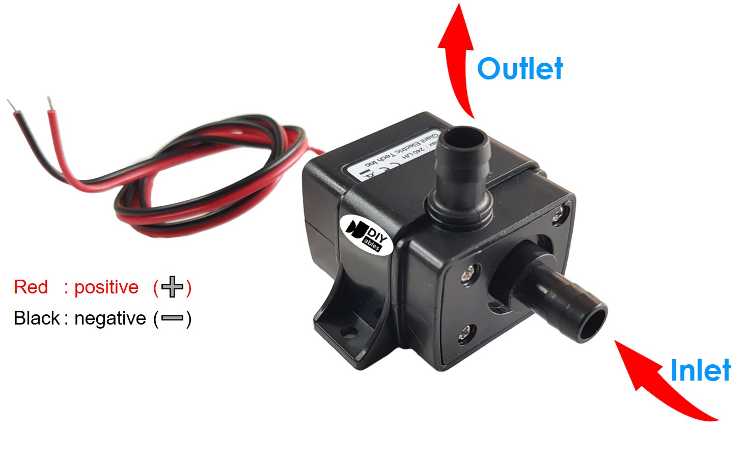
A pump that runs on 12 volts has two wires:
- Black wire (-): Attach this wire to the negative terminal of your 12V DC power supply.
- Red wire (+): Attach this wire to the positive terminal of your 12V DC power supply.
How to Control Pump using Arduino Nano 33 IoT
If you connect a 12V power supply to a pump, the pump will run. You can control the pump with code using the Arduino Nano 33 IoT. To do this, you need to use a relay between the pump and the Arduino board. There is a detailed tutorial about using a relay. The guide explains the hardware connections, how it works, how to wire it to the Arduino Nano 33 IoT, and shows example code. Learn more in the Arduino Nano 33 IoT - Relay tutorial.
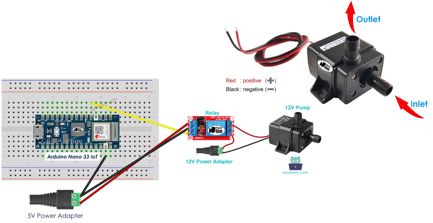
Wiring Diagram between Arduino Nano 33 IoT, Relay and Pump
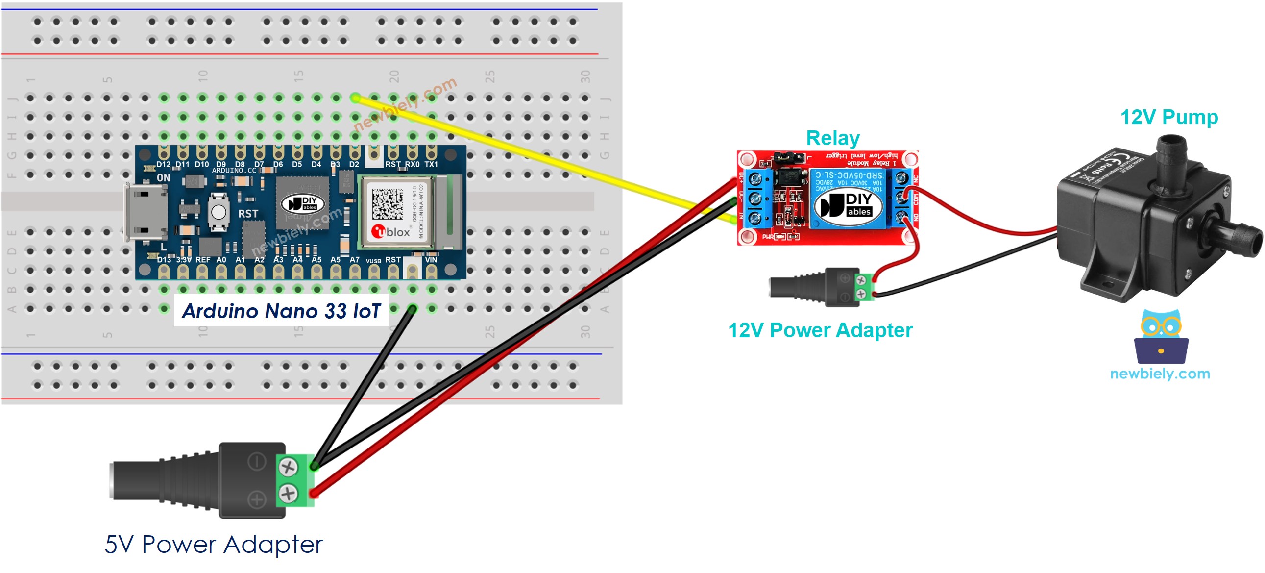
This image is created using Fritzing. Click to enlarge image
Arduino Nano 33 IoT - Pump Code
The code below turns the pump on and off every 4 seconds.
Detailed Instructions
If you are new to the Arduino Nano 33 IoT, be sure to check out our Getting Started with Arduino Nano 33 IoT tutorial. Then, follow these steps:
- Connect the components to the Arduino Nano 33 IoT board as depicted in the diagram.
- Use a USB cable to connect the Arduino Nano 33 IoT board to your computer.
- Launch the Arduino IDE on your computer.
- Select the Arduino Nano 33 IoT board and choose its corresponding COM port.
- Copy the above code and paste it into the Arduino IDE.
- Compile and upload the code to the Arduino Nano 33 IoT board by clicking the Upload button in the Arduino IDE.
- Check the pump’s status.
Line-by-line Code Explanation
The Arduino Nano 33 IoT code above explains each line. Please read the comments in the code!