Arduino Nano 33 IoT - Stepper Motor
In this lesson, we will learn how to use the Arduino Nano 33 IoT board to control a stepper motor.
- How to use the L298N board to run a bipolar stepper motor
- How to set the stepper motor’s position
- How to adjust the stepper motor’s speed
- How to change the stepper motor’s direction
This guide works for any 4-wire bipolar stepper motor. Here, we use the NEMA 17 stepper motor as an example.
Hardware Preparation
Or you can buy the following kits:
| 1 | × | DIYables Sensor Kit (18 sensors/displays) |
Additionally, some of these links are for products from our own brand, DIYables .
Overview of Stepper Motor
There are two common kinds of stepper motors:
- Bipolar: These motors have 4 wires.
- Unipolar: These motors have 5 or 6 wires. For a 6-wire unipolar motor, you can use just 4 of the wires to control it as if it were a bipolar motor.
If you want to learn about a 5-wire unipolar stepper motor, check out the guide called Arduino Nano 33 IoT - Control 28BYJ-48 Stepper Motor Using ULN2003 Driver.
This guide is only for bipolar stepper motors.
Bipolar Stepper Motor pinout
A bipolar stepper motor has four pins. Different companies might use other names for these pins. Here is a table with some common names for them.
| PIN NO | Naming 1 | Naming 2 | Naming 3 |
|---|---|---|---|
| 1 | A+ | A | A |
| 2 | A- | A | C |
| 3 | B+ | B | B |
| 4 | B- | B | D |
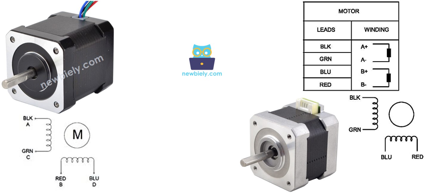
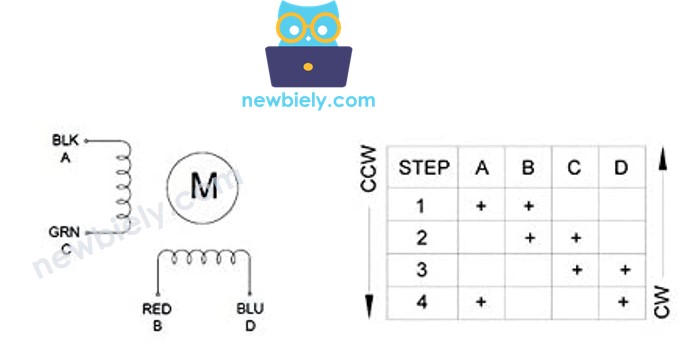
The setup of pins, the names of wires, and the colors of wires can vary by manufacturer. To know which wire color goes with which pin name, check the datasheet or user manual from the manufacturer. The picture above shows the details for two different motors, each with its own way of naming and coloring wires.
Steps per Revolution
The motor's details tell you how many degrees it moves with each step (we'll call this DEG_PER_STEP). Depending on how you control the motor, the number of steps for one full turn (we'll call this STEP_PER_REVOLUTION) is shown in the table below.
| Control method | Steps per Revolution | Real degree per step |
|---|---|---|
| Full-step | STEP_PER_REVOLUTION = 360 / DEG_PER_STEP | DEG_PER_STEP |
| Half-step | STEP_PER_REVOLUTION = (360 / DEG_PER_STEP) * 2 | DEG_PER_STEP / 2 |
| Micro-step (1/n) | STEP_PER_REVOLUTION = (360 / DEG_PER_STEP) * n | DEG_PER_STEP / n |
For example, if the motor's datasheet says that each step rotates 1.8 degrees:
| Control method | Steps per Revolution | Real degree per step |
|---|---|---|
| Full-step | 200 steps/revolution | 1.8° |
| Half-step | 400 steps/revolution | 0.9° |
| Micro-step (1/n) | (200 * n) steps/revolution | (1.8 / n)° |
How to control a stepper motor using Arduino Nano 33 IoT
The Arduino Nano 33 IoT can send signals to control the stepper motor, but these signals might not have enough voltage and current for the motor. Because of this, a separate hardware driver is needed to connect the Arduino Nano 33 IoT with the stepper motor. This driver does two main jobs:
- Boosting Control Signals: It increases the current and voltage from the Arduino Nano 33 IoT to make sure the stepper motor gets the power it needs.
- Protecting the Arduino Nano 33 IoT: At the same time, it keeps the Arduino Nano 33 IoT safe from the higher current and voltage used for the stepper motor, preventing damage.
There are many hardware controllers that you can use for stepper motors, and one popular option is the L298N Driver.
Overview of L298N Driver
One L298N Driver can control two DC motors or one stepper motor. In this guide, you'll learn how to use it to control a stepper motor.
L298N Driver Pinout
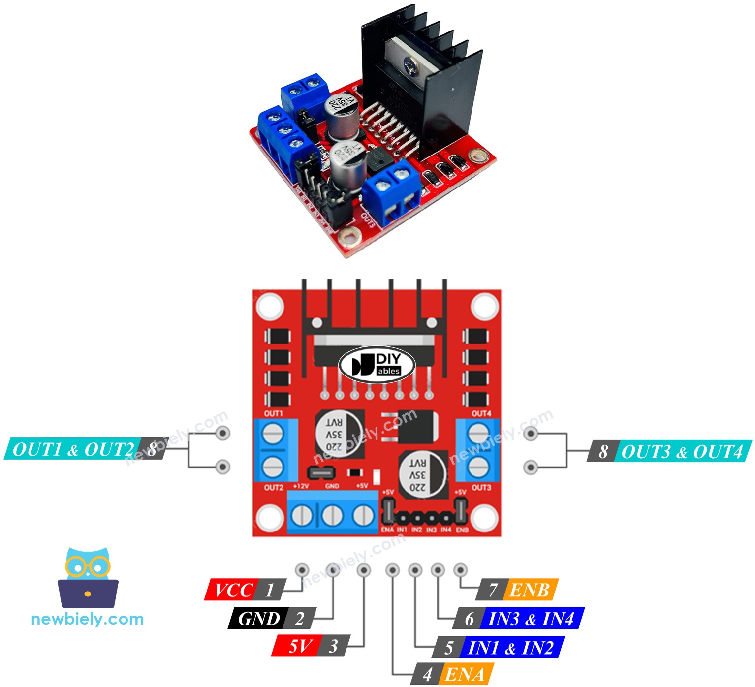
The L298N driver board has 11 pins and 3 jumpers.
- VCC pin: Provides power to the motor. It can use any voltage between 5V and 35V.
- GND pin: This is the ground pin. It must be connected to ground (0V).
- 5V pin: Provides power for the L298N module. You can use the 5V from the Arduino Nano 33 IoT.
- IN1, IN2, IN3, IN4 pins: Connect to the Arduino Nano 33 IoT. They receive the control signals that run the stepper motor.
- OUT1, OUT2, OUT3, OUT4 pins: Connect to the stepper motor.
- ENA and ENB jumpers: Used to turn on the stepper motor. Both jumpers should stay in place.
- 5V-EN jumper: If this jumper is in place, the L298N module gets power from the VCC pin, so nothing needs to be connected to the 5V pin. If you remove it, you must supply power to the L298N module through the 5V pin.
As mentioned earlier, the L298N driver uses two separate power inputs:
- One power supply for the stepper motor (using VCC and GND pins) should be between 5V and 35V.
- One power supply for the L298N module’s internal circuit (using the 5V and GND pins) should be between 5V and 7V. If the 5V-EN jumper is in place, you don't need to connect this power supply.
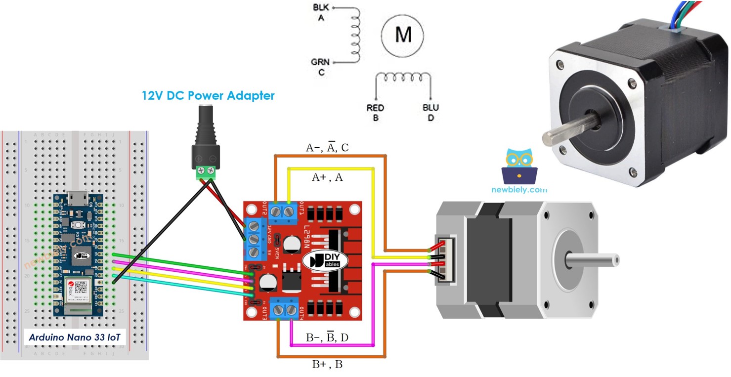
Wiring Diagram
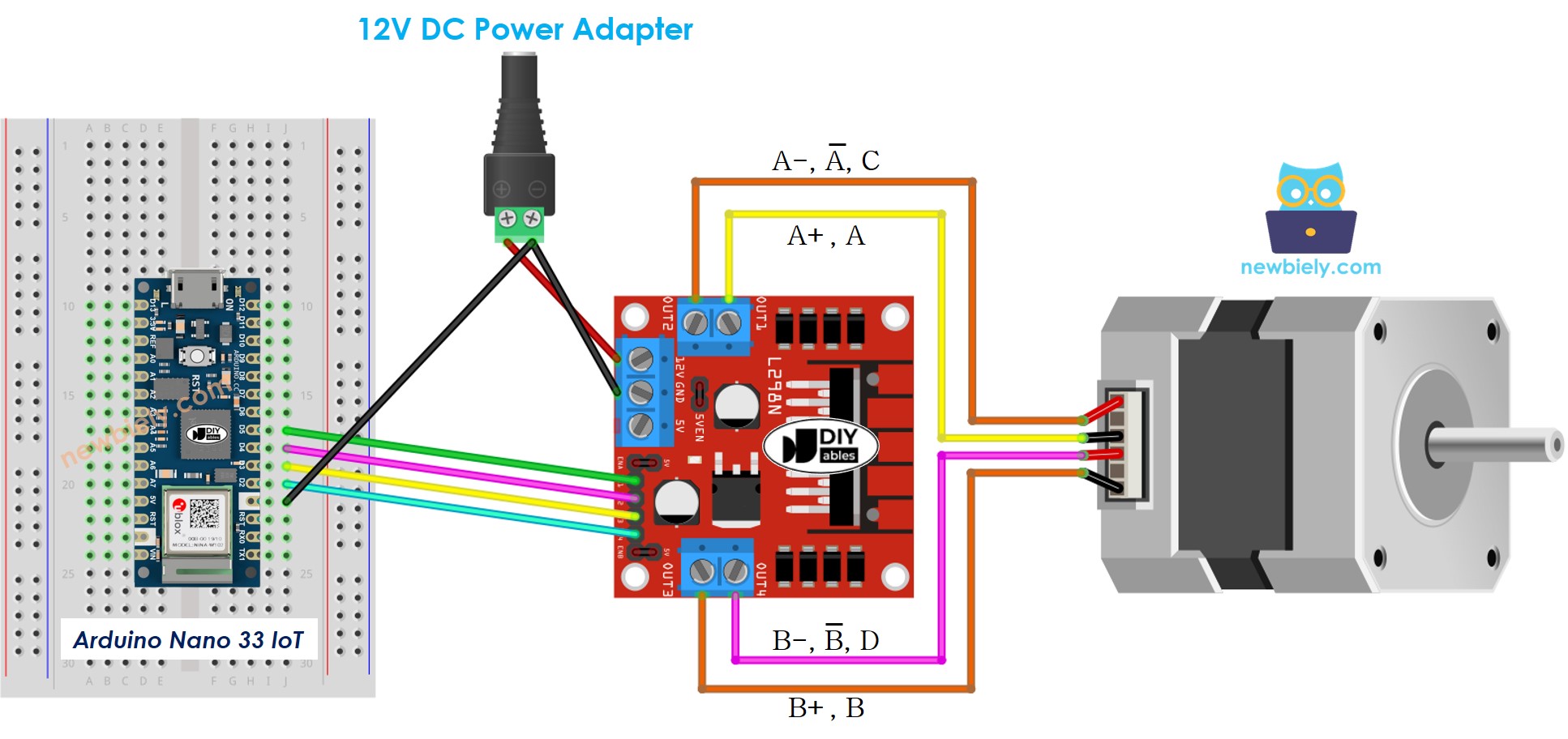
This image is created using Fritzing. Click to enlarge image
※ NOTE THAT:
Keep all three jumpers on the L298N module in place if the motor's power supply is 12V or less.
The order of the pins on stepper motors can be different for each manufacturer. Check the table below to make sure you have the right wiring.
Wiring table between Arduino Nano 33 IoT and L298N Driver
| Arduino Nano 33 IoT pins | L298N pins |
|---|---|
| D5 | IN1 |
| D4 | IN2 |
| D3 | IN3 |
| D2 | IN4 |
Wiring table between L298N Driver and Stepper motor
Important: Don't worry about the order of the wires on the stepper motor shown in the diagram above. It is just an example. The pin order on stepper motors can be different for each manufacturer. Always follow the wiring order in the table below.
| L298N pins | Stepper motor pins | Or | Or |
|---|---|---|---|
| OUT1 | A+ | A | A |
| OUT2 | A- | A | C |
| OUT3 | B+ | B | B |
| OUT4 | B- | B | D |
Before you buy a stepper motor, check its datasheet, specifications, or manual. Make sure it shows which pin color matches which pin name. For example, this stepper motor (LINK_MAIN_STEPPER_MOTOR_NEMA_17) shows the mapping in the image below.
According to that mapping, the wiring table looks like this:
| L298N pins | stepper motor pins | wire color |
|---|---|---|
| OUT1 | A | black wire |
| OUT2 | C | green wire |
| OUT3 | B | red wire |
| OUT4 | D | blue wire |
※ NOTE THAT:
For every wiring table shown above for connecting the stepper motor to the L298N Driver, you can switch OUT1 with OUT2 and OUT3 with OUT4. This means there are different ways to connect the wires. But if you do that, the motor might spin in the opposite direction (if it was spinning one way, it will spin the other way).
How to control a Stepper motor using an L298N driver.
Controlling a stepper motor is not easy, especially if you want to do other tasks while it runs. Thankfully, the AccelStepper library makes it very simple.
The Arduino IDE comes with a built-in Stepper library. However, we don't suggest using this library because:
- The library has a feature that stops other tasks. This means that while it controls the stepper motor, the Arduino Nano 33 IoT cannot do anything else.
- It does not offer enough features.
We suggest you use the AccelStepper library instead. This library works with:
- Speeding up
- Slowing down
- Using full steps or half steps
- Controlling several stepper motors at the same time, with each motor stepping independently
- Problem: Does not support very small (micro) steps
How To Control the Position of Stepper Motor via L298N Driver
We can move the stepper motor to the position we want by using:
※ NOTE THAT:
The stepper.moveTo() function does not block other processes. This is a strong advantage of this library, but there are some things to keep in mind when using it:
- Call stepper.run() as often as you can. It should be used inside the void loop() function.
- Do not use the delay() function while the motor is moving.
- Do not use Serial.print() or Serial.println() functions while the motor is moving. These functions can slow down the stepper motor.
How To Control the Speed of Stepper Motor via L298N Driver
We can control not just speed, but also how fast it speeds up or slows down using some simple tools.
How To Control the Direction of Stepper Motor via L298N Driver
If you connect the wires as shown above, the motor will turn in:
- Clockwise direction: When we move the motor from a lower position to a higher position (increasing position).
- Anticlockwise direction: When we move the motor from a higher position to a lower position (decreasing position).
For instance:
- When the motor is at position 100 and we set it to 200, it turns to the right (clockwise).
- When the motor is at position -200 and we set it to -100, it turns to the right (clockwise).
- When the motor is at position 200 and we set it to 100, it turns to the left (anticlockwise).
- When the motor is at position -100 and we set it to -200, it turns to the left (anticlockwise).
※ NOTE THAT:
As mentioned earlier, if you switch OUT1 with OUT2 or OUT3 with OUT4, the position might go up in a counterclockwise direction and go down in a clockwise direction.
How To Stop Stepper Motor
- The stepper motor will stop by itself when it reaches the right spot.
- You can also make the stepper motor stop right away using the stepper.stop() function.
Arduino Nano 33 IoT Code - Stepper Motor Code
The code below does the following:
- Turn the motor one full turn to the right.
- Wait for 5 seconds.
- Turn the motor one full turn to the left.
- Wait for 5 seconds.
- This process repeats over and over again.
Detailed Instructions
If you are new to the Arduino Nano 33 IoT, be sure to check out our Getting Started with Arduino Nano 33 IoT tutorial. Then, follow these steps:
- Connect the components to the Arduino Nano 33 IoT board as depicted in the diagram.
- Use a USB cable to connect the Arduino Nano 33 IoT board to your computer.
- Launch the Arduino IDE on your computer.
- Select the Arduino Nano 33 IoT board and choose its corresponding COM port.
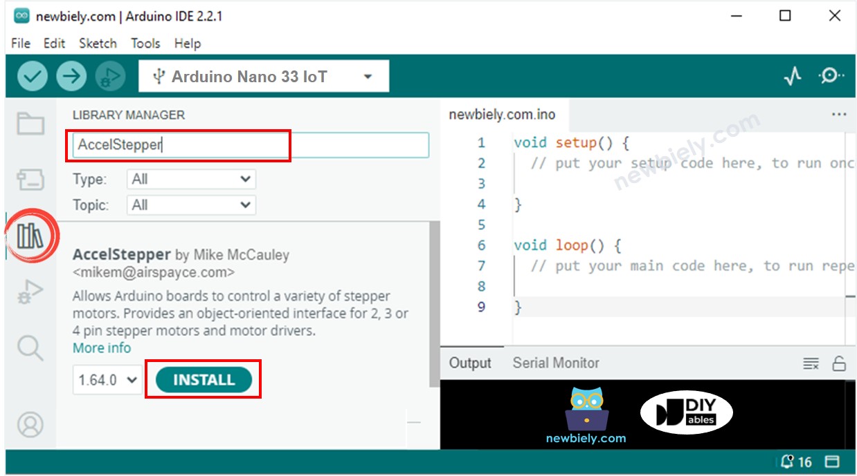
- Open the Library Manager by clicking the Library Manager icon on the left side of the Arduino IDE.
- In the search box, type AccelStepper and find the AccelStepper library by Mike McCauley.
- Click the Install button to add the AccelStepper library.
- Copy the code above and open it in the Arduino IDE.
- Click the Upload button in the Arduino IDE to send the code to your Arduino Nano 33 IoT.
- You will see the following actions happen:
- The stepper motor makes one full turn clockwise.
- The stepper motor stops for 5 seconds.
- The stepper motor makes one full turn counterclockwise.
- The stepper motor stops for 5 seconds.
- This process repeats over and over.
- You can view the results on the Serial Monitor.
Code Explanation
Please read every explanation shown in the comment parts of the code!