Arduino Nano 33 IoT - Joystick
In this guide, you'll learn how to use a joystick with the Arduino Nano 33 IoT. We will cover the following topics:
- How a joystick works
- How to connect a joystick to an Arduino Nano 33 IoT and program it
- How to change the joystick's readings into control signals like X and Y positions, angle, and how to move a motor up, down, left, or right
Hardware Preparation
Or you can buy the following kits:
| 1 | × | DIYables Sensor Kit (18 sensors/displays) |
Additionally, some of these links are for products from our own brand, DIYables .
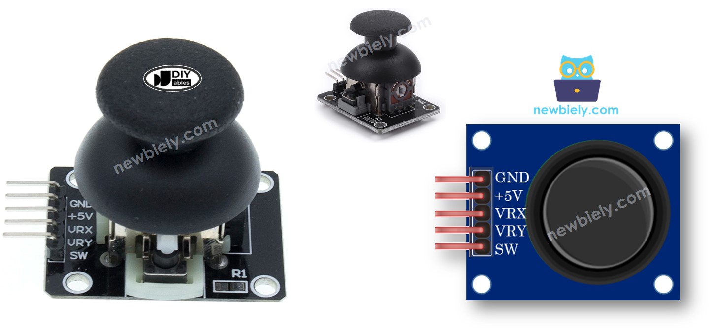
Overview of Joystick Sensor
You have probably seen a joystick before. It might be on a video game controller, a toy controller, or even on a large machine like the one used to control an excavator.
The joystick has two potentiometers arranged at right angles to each other and one push button. This means it provides the following outputs:
- An analog number between 0 and 4095 showing the left-right position (called the X-coordinate).
- An analog number between 0 and 4095 showing the up-down position (called the Y-coordinate).
- A digital reading from a pushbutton, which can be either HIGH or LOW.
Using two analog values together creates 2-D coordinates, with the center point being the value when the joystick is at rest. The exact direction of these coordinates can be easily found by running a test program in the next section.
Some programs might use all three outputs, while others might only use a few of them.
Pinout
A joystick has five pins:
- GND pin: Connect this to GND (0V).
- VCC pin: Connect this to VCC (3.3V).
- VRX pin: This gives an analog signal that shows the horizontal (X-axis) position.
- VRY pin: This gives an analog signal that shows the vertical (Y-axis) position.
- SW pin: This comes from the joystick’s button. It is usually not connected. When you add a pull-up resistor, the SW pin will be HIGH (on) when the button is not pressed and LOW (off) when it is pressed.
How It Works
- When you move the joystick left or right, the voltage on the VRX pin changes between 0 and 3.3V. Pushing it fully left gives 0V and fully right gives 3.3V. The Arduino Nano 33 IoT reads a value between 0 and 4095 on its analog pin depending on the position.
- When you move the joystick up or down, the voltage on the VRY pin also changes between 0 and 3.3V. Fully up is 0V and fully down is 3.3V. The Arduino Nano 33 IoT reads a value between 0 and 4095 on its analog pin based on how far you push it.
- When you push the joystick in any direction, the voltages on both the VRX and VRY pins change in proportion to how much you move along each axis.
- When you press down on the joystick, the built-in pushbutton is activated. If you use a pull-up resistor on the SW pin, the voltage on that pin will change from 3.3V to 0V, so the Arduino Nano 33 IoT’s digital pin will detect a change from HIGH to LOW.
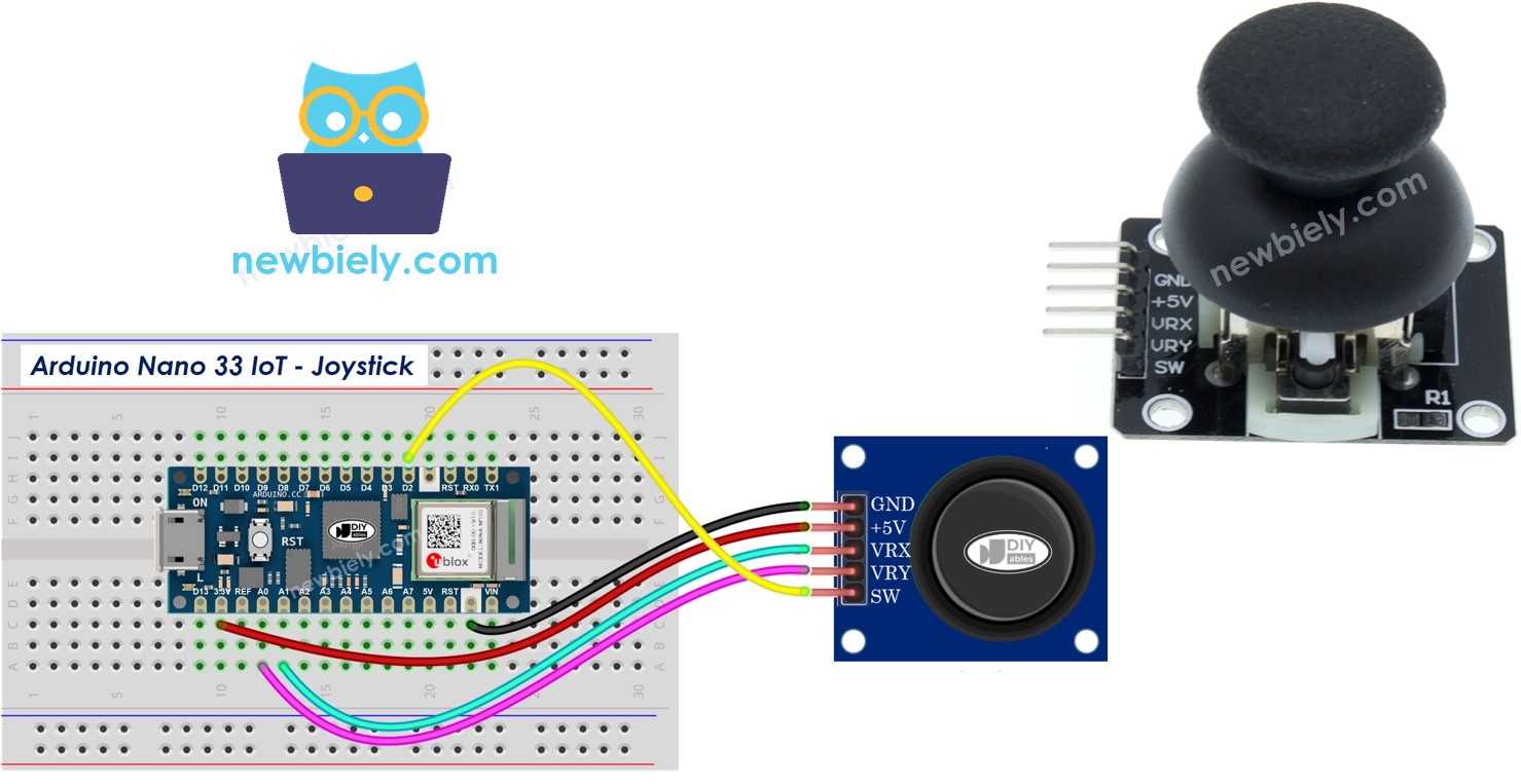
Wiring Diagram
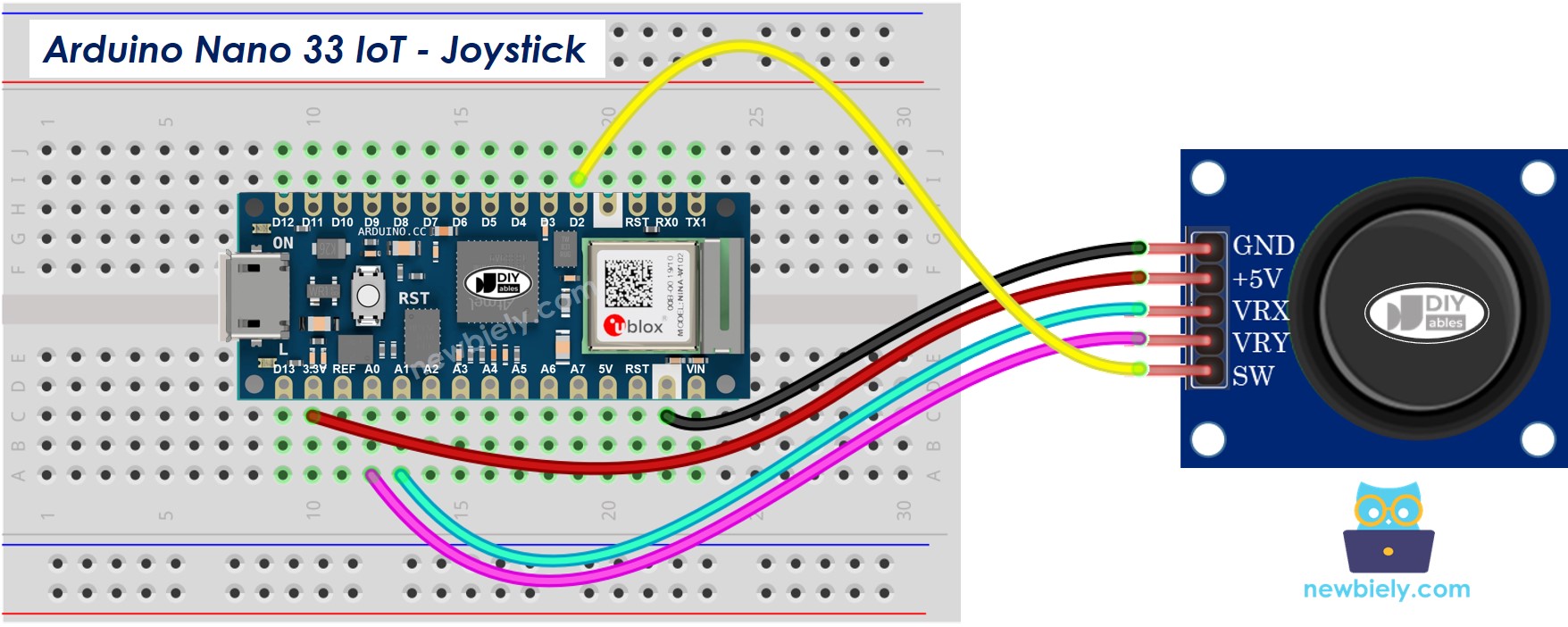
This image is created using Fritzing. Click to enlarge image
※ NOTE THAT:
Please note that the Arduino Nano 33 IoT pins A4 and A5 have built-in pull-up resistors for I2C communication:
- This can affect analog readings, so it is recommended to avoid using these pins with any devices/sensors that relies on ADC.
- Although these pins can be used as digital input pins, it is recommended to avoid using them for digital input. If you must use them, do NOT use internal or external pull-down resistors for these pins.
How To Program For Joystick
The joystick has two parts: an analog stick that moves in two directions (X and Y) and a digital button you press.
- For the analog parts (X and Y directions), you only need to read the value from the analog input pin by using the analogRead() function.
- For the digital section (pushbutton): This is a button. The easiest and most convenient way is to use the ezButton library. This library takes care of button bouncing and also turns on an internal pull-up resistor. You can find more information about the button in the Arduino Nano 33 IoT - Button tutorial. The code will be shown in the next part of this guide.
After reading numbers from analog pins, we might have to change them into values we can control. The next part will show sample code for this.
Arduino Nano 33 IoT Code
In this section, you'll see these sample codes for the Arduino Nano 33 IoT.
- Example code: reads number values from a joystick
- Example code: reads number values and checks the joystick button state
- Example code: changes number values into commands like MOVE_LEFT, MOVE_RIGHT, MOVE_UP, and MOVE_DOWN
- Example code: changes number values to angles to control two servo motors (for example, in a pan-tilt camera)
Reads analog values from joystick
Detailed Instructions
If you are new to the Arduino Nano 33 IoT, be sure to check out our Getting Started with Arduino Nano 33 IoT tutorial. Then, follow these steps:
- Connect the components to the Arduino Nano 33 IoT board as depicted in the diagram.
- Use a USB cable to connect the Arduino Nano 33 IoT board to your computer.
- Launch the Arduino IDE on your computer.
- Select the Arduino Nano 33 IoT board and choose its corresponding COM port.
- Copy the given code and open it in the Arduino IDE.
- Press the Upload button in the Arduino IDE to send the code to your Arduino Nano 33 IoT.
- Push the joystick all the way in one direction, then move it in a circle (either clockwise or anticlockwise).
- Look at the Serial Monitor to see the results.
- While moving the joystick with your thumb, keep an eye on the Serial Monitor.
- If the X value is 0, note that spot as the left side (the opposite side is right).
- If the Y value is 0, note that spot as the top (the opposite side is down).
You might see that the value does not match how you move the joystick. The problem is not the joystick, but the ADC on the Arduino Nano 33 IoT. We will explain why this happens at the end of this guide.
Reads analog values and reads the button state from a joystick
Detailed Instructions
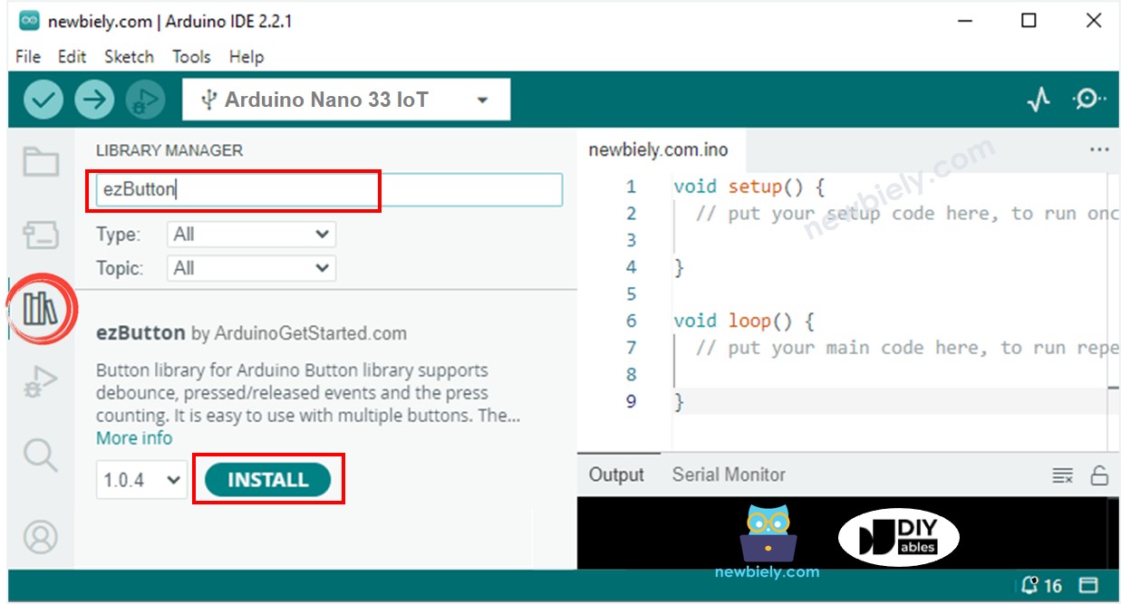
- Open the Library Manager by clicking the Library Manager icon on the left side of the Arduino IDE.
- Type ezButton into the search box, then look for the button library by ArduinoGetStarted.com.
- Click the Install button to add the ezButton library.
- Copy the code above and open it in the Arduino IDE.
- Click the Upload button in the Arduino IDE to send the code to your Arduino Nano 33 IoT.
- Move the joystick to the left, right, up, or down.
- Press the top of the joystick.
- See the results in the Serial Monitor.
Converts analog value to MOVE LEFT/RIGHT/UP/DOWN commands
Detailed Instructions
- Copy the code above and open it in the Arduino IDE
- Click the Upload button in the Arduino IDE to send the code to the Arduino Nano 33 IoT
- Move the joystick in any direction: left, right, up, down, or any angle
- See the result in the Serial Monitor
※ NOTE THAT:
Sometimes, there might be no command, one command, or two commands at the same time (for example, UP and LEFT together).
Converts analog values to angles to control two servo motors
More information is available in the Arduino Nano 33 IoT - Joystick Controls Servo Motor tutotial.