
Arduino Mega - Slide Switch
Imagine an escape-room puzzle box with a row of small levers on the lid. The box opens only when every lever is set the right way. Or think of a greenhouse controller with a "manual / auto" lever, or a test rig with a "slow / fast" lever. Each lever is a slide switch: you push the handle to one side, and it stays there until you push it back. With 54 digital pins, the Arduino Mega has room for a lot of them. This tutorial instructs you how to use the Arduino Mega to read one DIYables Mini Slide Switch SS12D10 and report whether it is ON or OFF. In detail, we will learn:
- How the SPDT contacts inside the SS12D10 join its middle pin to one of the two outer pins
- How to connect the slide switch to digital pin 7 of the Arduino Mega with three wires and no resistor
- How to program the Arduino Mega to print the switch state at start-up and after every move, with a 50 ms check against contact bounce
- How to remove the 5V wire and use INPUT_PULLUP instead, and why ON and OFF then trade places
We suggest:
- Checking the Arduino Mega - Switch tutorial if your project needs a large ON/OFF rocker switch that mounts in a hole of a case.
- Checking the Arduino Mega - DIP Switch tutorial if you want many tiny switches in one package, for example to set an address.
- Checking the Arduino Mega - Button Module tutorial if the input should spring back as soon as you take your finger away.
Hardware Preparation
Or you can buy the following kits:
| 1 | × | DIYables Sensor Kit (18 sensors/displays) |
Additionally, some of these links are for products from our own brand, DIYables .
Overview of Slide Switch and Its Pinout
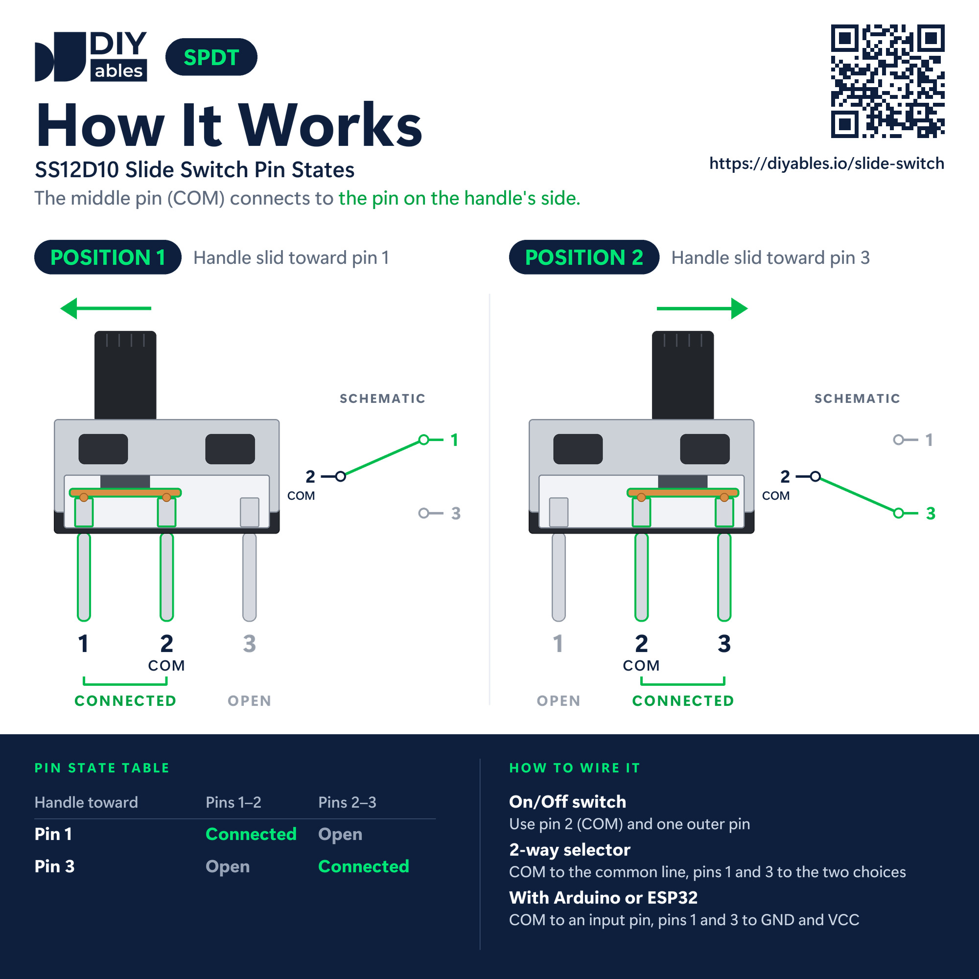
The DIYables Mini Slide Switch SS12D10 is a small plastic block with a 5mm handle on top and three legs underneath. You push the handle toward one end, and it latches there. It does not spring back like a push button. So the Arduino Mega can read the same position again and again, until somebody moves the handle.
The contact type is SPDT, short for single pole, double throw. Some shops write it as 1P2T. Inside the body, a little metal bridge slides together with the handle. The bridge always rests on the middle leg, and it also reaches the outer leg on the handle's side. As a result, the middle leg is joined to exactly one outer leg at any time.
| DIYables SS12D10 | |
|---|---|
| Positions | 2 (latching) |
| Contact Type | SPDT (1P2T) |
| Number of Pins | 3, vertical through-hole |
| Pin Spacing | 4.7mm |
| Pin Length | 6.9mm |
| Handle | 5mm |
| Body Dimensions | about 12.8 x 6.7 x 18.2mm |
| Contact Material | silver-plated brass |
| Contact Rating | AC 125V 2A |
| Mechanical Life | more than 100,000 switching cycles |
| Working Temperature | -25°C to 80°C |
The AC 125V 2A rating tells you the limit of the contacts, nothing more. In this project, the switch only carries a tiny signal current into one input pin of the Arduino Mega, far below that limit.
The three legs and their jobs in this tutorial:
- Pin 1 (one end of the row): must be connected to GND (0V)
- Pin 2, COM (the middle leg): must be connected to a digital input pin of the Arduino Mega. It passes on the voltage of whichever outer leg the bridge touches
- Pin 3 (the other end of the row): must be connected to the 5V pin of the Arduino Mega for the 3-wire wiring. In the 2-wire wiring, this leg gets no wire
What each handle position does, and what the Arduino Mega reads with the 3-wire wiring:
| Handle Position | Joined Pins | Open Pin | Pin 7 Reads |
|---|---|---|---|
| Position 1 - toward pin 1 | Pin 1 and COM | Pin 3 | LOW (OFF) |
| Position 2 - toward pin 3 | COM and Pin 3 | Pin 1 | HIGH (ON) |
※ NOTE THAT:
You will not find any marks next to the legs of the SS12D10. Find COM by its place: it is always the leg in the middle. Pin 1 and pin 3 look exactly the same. In this tutorial, pin 1 is simply the outer leg that gets the GND wire. Swapping the two outer wires does no harm - only the ON side and the OFF side of the handle change places.
Wiring Diagram
Three jumper wires are enough. The middle leg (COM) goes to digital pin 7, pin 1 goes to one of the GND pins, and pin 3 goes to the 5V pin of the Arduino Mega. Since COM always touches either 5V or GND, pin 7 is never left floating, and no pull-up or pull-down resistor is needed.
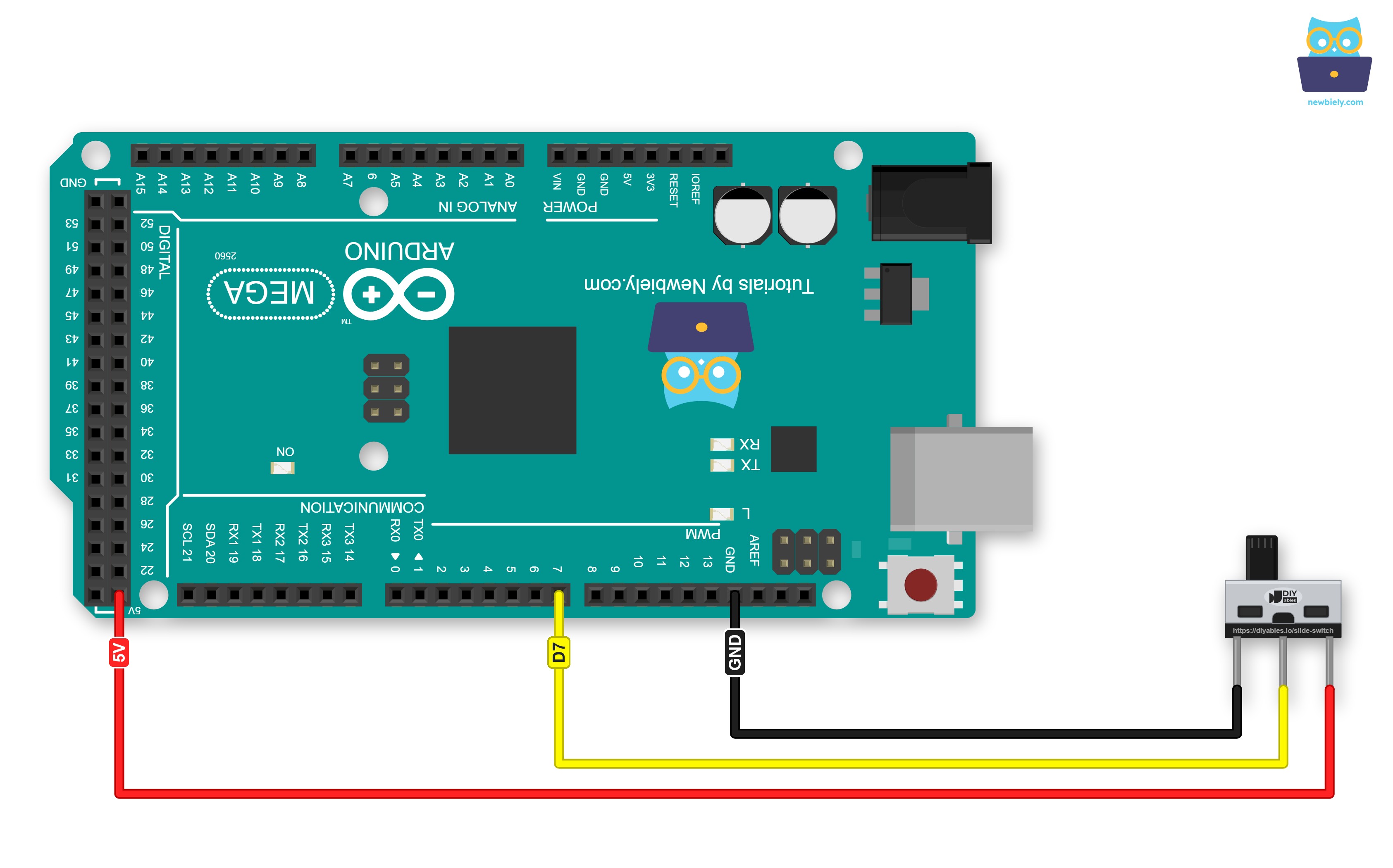
This image is created using Fritzing. Click to enlarge image
| Slide Switch Pin | Arduino Mega Pin |
|---|---|
| Pin 1 | GND |
| Pin 2 (COM) | Pin 7 |
| Pin 3 | 5V |
※ NOTE THAT:
- The Arduino Mega is a 5V board: its ATmega2560 chip works with 5V logic. That is why pin 3 of the switch goes to 5V. The 3.3V pin of the Mega is not used here.
- Leave pin 7 as an INPUT in every sketch you upload. Never set it to OUTPUT: the switch connects the pin straight to 5V or GND, and an output that drives the opposite level would cause a short circuit and could damage the pin.
How To Program For Slide Switch
A slide switch needs no library. The built-in functions of the Arduino IDE are enough.
- The first step is to give digital pin 7 a clear name, so the code shows what is wired there:
- Next, make that pin an input inside setup() with pinMode(). Plain INPUT is the right mode, because the switch drives the pin HIGH or LOW by itself:
- Read the level with digitalRead(). HIGH means the handle is on the pin 3 side, LOW means it is on the pin 1 side:
- While the handle moves, the metal contacts touch and let go several times within a few milliseconds. This is called bounce. To ignore it, compare each new reading with the last accepted one. When they differ, wait 50 milliseconds and read the pin again before you accept the change:
Arduino Mega Code for Slide Switch - Print ON/OFF on Each Move
This sketch has two jobs. In setup(), it reports where the handle is when the board starts. In loop(), it keeps an eye on pin 7 and prints a new line only after the handle has really moved and passed the 50 ms check.
Detailed Instructions
- New to the Arduino Mega? First, follow how to set up the Arduino IDE for the Arduino Mega.
- Wire the components as shown in the diagram.
- Connect the Arduino Mega board to your computer using a USB cable.
- Open Arduino IDE on your computer.
- Pick Arduino Mega or Mega 2560 as the board, then pick the COM port of the Mega.
- Copy the code above and paste it into an empty sketch.
- Click the Upload button.
- Push the handle toward pin 3, then open the Serial Monitor at 9600 baud. If the first two lines do not appear, press the RESET button on the Mega.
- Slide the handle toward pin 1, toward pin 3, toward pin 1, and toward pin 3 again.
The second line is the start-up position. After that, four moves give exactly four lines. Would you like the pin 1 side to be ON? Swap the GND and 5V wires on the two outer legs - the code stays the same.
Does the Serial Monitor jump between ON and OFF while you do not touch the switch? Then the GND wire or the 5V wire is loose, and pin 7 is floating. Push both wires in firmly.
Arduino Mega Code for Slide Switch - Two Wires with INPUT_PULLUP
Every digital pin of the ATmega2560 has a pull-up resistor inside the chip. With INPUT_PULLUP, that resistor holds pin 7 at HIGH whenever COM is not joined to anything. So the 5V wire on pin 3 can go. This helps when the switch sits on a front panel far away from the board, or when the 5V pin already feeds other modules.
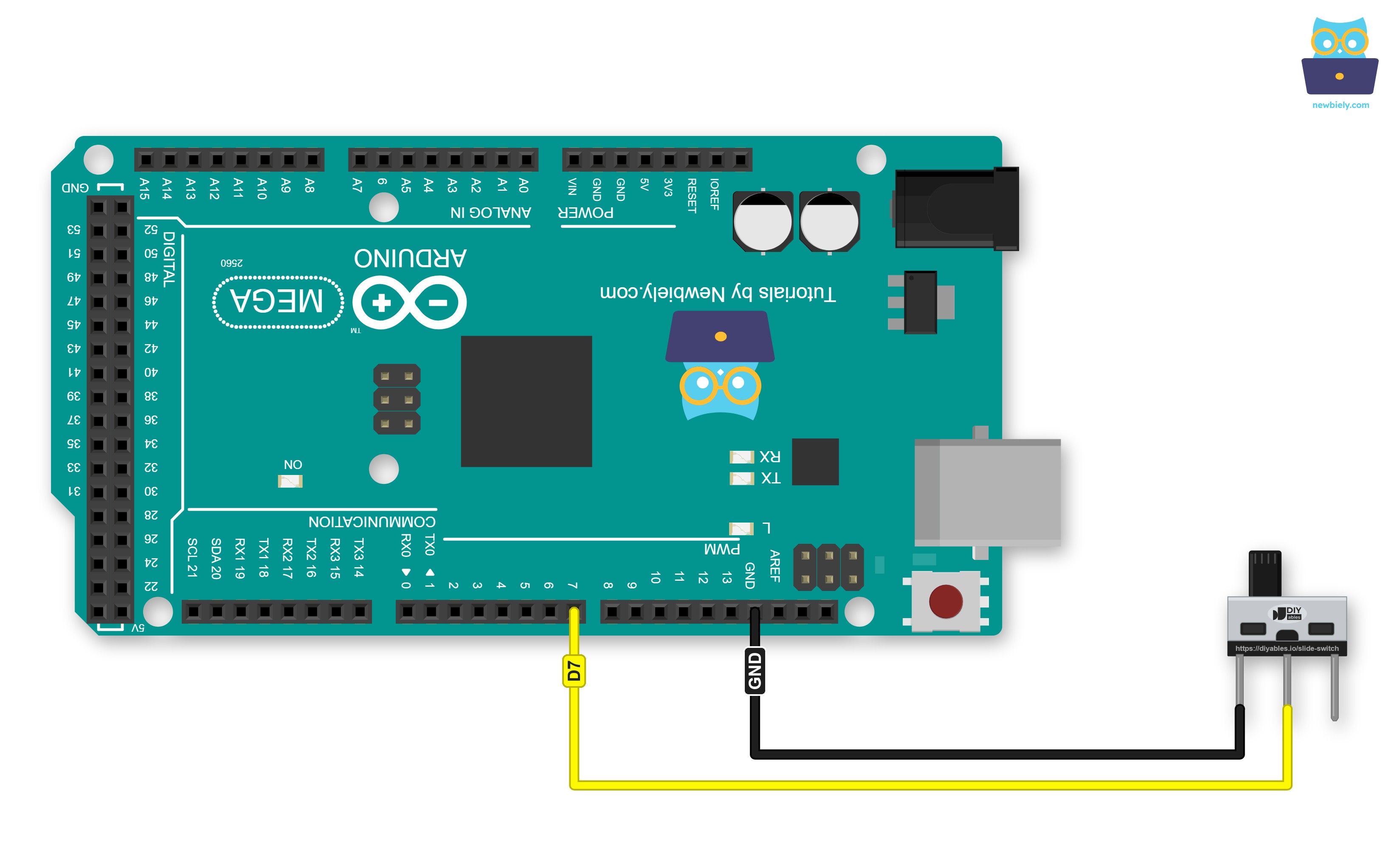
This image is created using Fritzing. Click to enlarge image
| Slide Switch Pin | Arduino Mega Pin |
|---|---|
| Pin 1 | GND |
| Pin 2 (COM) | Pin 7 |
| Pin 3 | not connected |
Be careful: with this wiring, the logic is the opposite of the first sketch.
| Handle Position | Pin 7 Reads | The Code Prints |
|---|---|---|
| Toward pin 1 (COM joined to GND) | LOW | ON |
| Toward pin 3 (COM open, pulled up) | HIGH | OFF |
In short, LOW means ON when you use INPUT_PULLUP.
Detailed Instructions
- Take the wire off pin 3 of the switch. The COM wire and the GND wire stay where they are.
- Paste the code above into the Arduino IDE in place of the first sketch, and click Upload.
- Open the Serial Monitor. The handle is still on the pin 3 side, so the first state line now says OFF.
- Move the handle toward pin 1, toward pin 3, and toward pin 1 once more.
The same handle position that gave ON in the 3-wire test now gives OFF. Nothing is wrong - this is the flipped logic of INPUT_PULLUP.
Additional Knowledge
3 Wires or 2 Wires?
| 3 Wires (INPUT) | 2 Wires (INPUT_PULLUP) | |
|---|---|---|
| Wires to the switch | COM, pin 1 and pin 3 | COM and pin 1 only |
| Pin mode in the code | INPUT | INPUT_PULLUP |
| Handle toward pin 3 | HIGH = ON | HIGH = OFF |
| Handle toward pin 1 | LOW = OFF | LOW = ON |
| What holds pin 7 HIGH | the 5V pin, through the switch | the weak resistor inside the chip |
| 5V pin of the Mega | used by the switch | free for other parts |
It is evident that the 3-wire wiring gives the strongest signal and the more natural logic (HIGH = ON), while the 2-wire wiring saves one wire and keeps the 5V pin free. For short wires on a desk, both work equally well.
Many Slide Switches on One Arduino Mega
Each extra slide switch needs only its own input pin. All switches can share the GND wire, and in the 3-wire wiring also the 5V wire. For example, eight switches on pins 22 to 29 can set an 8-bit number from 0 to 255, just like a DIP switch, but with bigger handles that are easier to move by hand. For the escape-room box from the start of this page, the sketch would simply check that every pin reads the expected level before it opens the lock.
If you need a key that returns by itself after each press, use a push button instead of a slide switch.