
Arduino Mega - BTS7960 Motor Driver
In many tutorials, an electric hoist hangs from a beam. It raises a box of tools to a high shelf, stops, and later lets it back down. The motor of a hoist like that is a big 12V or 24V gear motor, and it draws much more current than the small motor drivers that most beginners start with can give. This is the kind of job the BTS7960 motor driver module was made for. This tutorial instructs you how to use the Arduino Mega 2560 with the BTS7960 to run one large DC motor forward and backward, fast or slow. In detail, we will learn:
- A look at the BTS7960 board, and the job of its RPWM, LPWM, R_EN, L_EN, VCC and GND pins
- Which pin levels make the motor lift (forward), lower (reverse), stop at once (brake) or spin down freely (coast)
- Where the six control wires go on the Arduino Mega, and which screw terminals take the supply and the motor
- How to write an Arduino Mega sketch that ramps the speed, stops, reverses and switches the driver off - one full hoist cycle
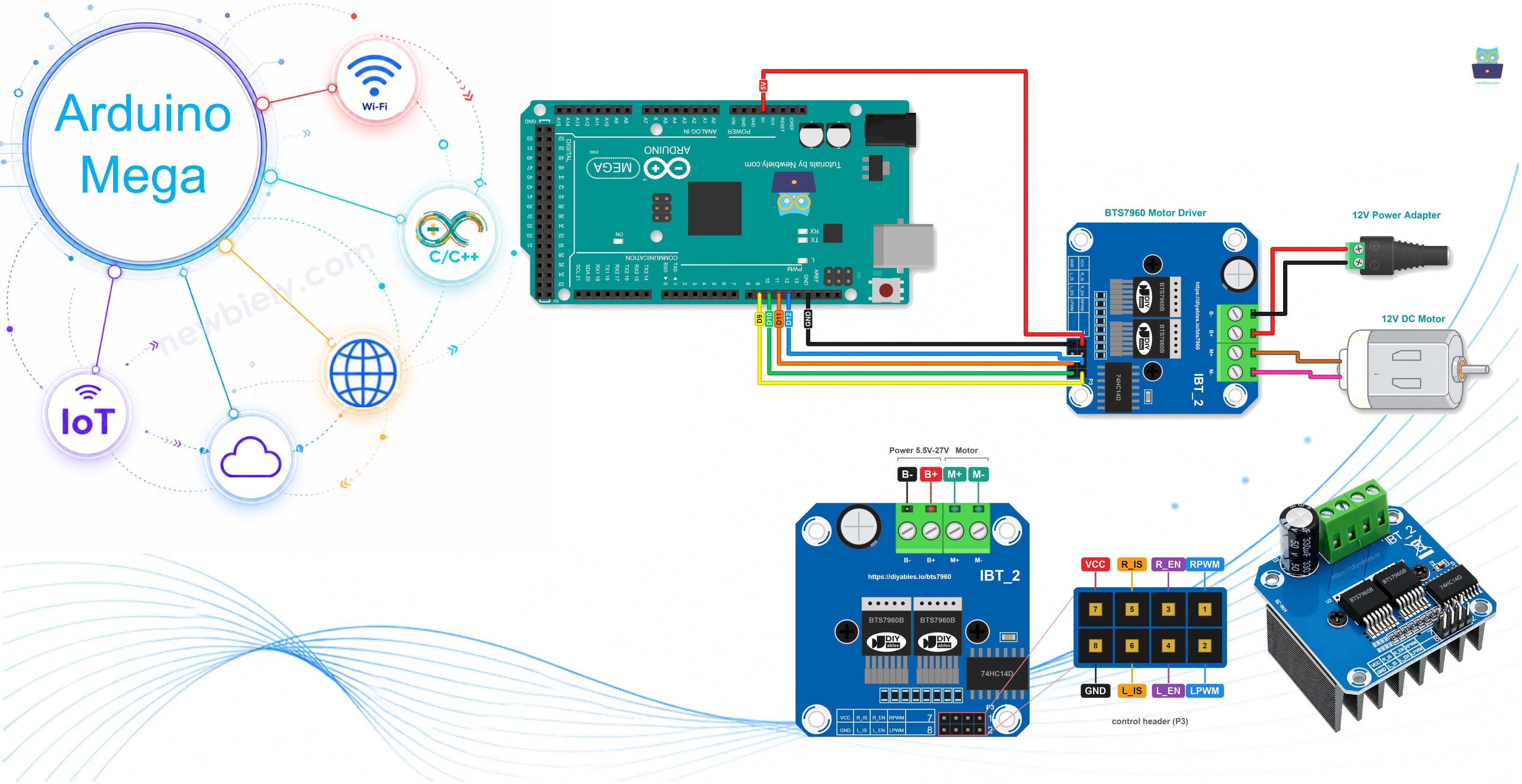
We suggest:
- Reading the Arduino Mega - DRV8833 DC Motor Driver page when your project has two small motors of 10.8V or less.
- Reading the Arduino Mega - DC Motor page for the basics of speed and direction with a small 5V motor and the DRV8833.
Hardware Preparation
Or you can buy the following kits:
| 1 | × | DIYables Sensor Kit (18 sensors/displays) |
Additionally, some of these links are for products from our own brand, DIYables .
Look for the current printed on the label of your motor. Your 12V adapter should be rated for a higher current than that number.
Overview of BTS7960 Motor Driver and Its Pinout
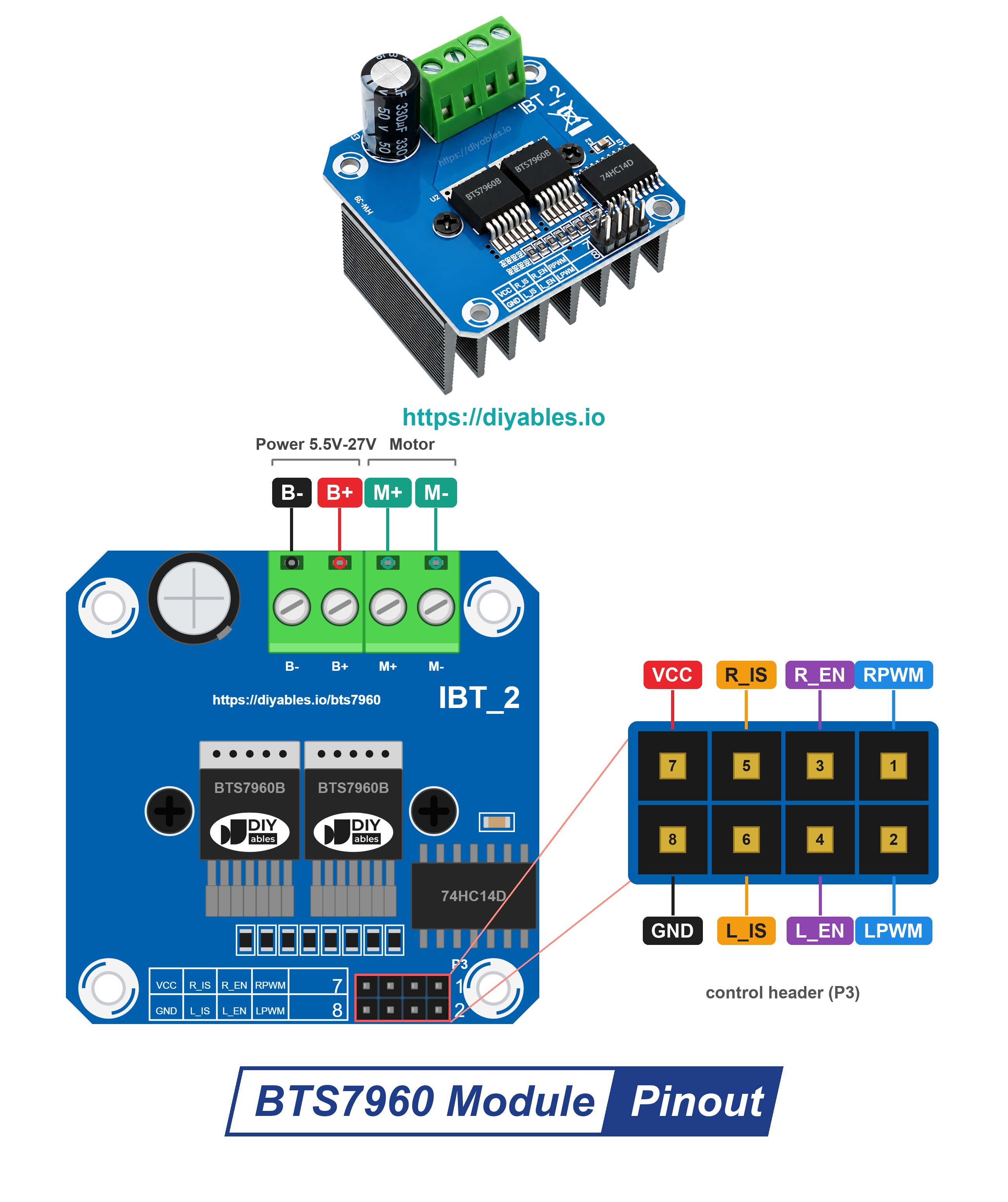
The BTS7960 module drives just ONE brushed DC motor, but a large and hungry one. Many sellers call the same board IBT-2 or HW-039. Two Infineon BTS7960B half-bridge chips are soldered on its top side, and a large heat sink below the board cools them. Each half-bridge decides whether its motor wire sees B+ or B-. Working as a pair, the two halves form a full H-bridge: when the right half drives the motor, it turns forward; when the left half drives it, it turns in reverse. Speed is set with PWM: the Mega flicks the signal ON and OFF hundreds of times per second, and the longer each ON part lasts, the faster the motor runs. A small 74HC14 buffer chip stands in the middle, so the pins of the Mega never drive the big power chips directly.
| BTS7960 Motor Driver Module | |
|---|---|
| H-bridge | built from two BTS7960B half-bridge chips by Infineon |
| Motors per module | a single brushed DC motor (forward + reverse) |
| Motor voltage between B+ and B- | anything from 5.5V to 27V DC, good for 6V, 12V and 24V motors |
| Maximum current | 43A, where the chip begins to limit it |
| Highest PWM frequency on RPWM / LPWM | 25 kHz |
| Built-in protection | current limit and over-temperature |
| Input buffer | 74HC14, powered through VCC |
| Control pins | 2 rows of 4 male header pins |
Do not read 43A as the current the board can give all day. It is the point where the chip begins to hold the current back. If your motor works for a long time without a break, keep its current far lower. For such long runs, how big the heat sink is decides what the module can take.
Here is how the labels pair up on the 2 x 4 header:
| Pin pair | Top row | Bottom row |
|---|---|---|
| 7 and 8 | VCC | GND |
| 5 and 6 | R_IS | L_IS |
| 3 and 4 | R_EN | L_EN |
| 1 and 2 | RPWM | LPWM |
The 8 pins of the header, one by one:
- RPWM pin: must be connected to Mega pin 9 or another PWM pin. This is the "forward" input: the wider the PWM pulses, the faster the motor turns that way.
- LPWM pin: must be connected to one more PWM-capable pin, pin 10 in this tutorial. It is the "reverse" input and works the same way in the other direction.
- R_EN pin: must be connected to an output pin of the Mega (pin 12 here). It is the on/off switch of the right half-bridge: LOW = off, HIGH = on.
- L_EN pin: must be connected to an output pin of the Mega (pin 11 here). It switches the left half-bridge on and off in the same way.
- R_IS and L_IS pins (printed R_S and L_S on some boards): these report the current and errors. Our hoist demo has no need for them, so both of them are left open.
- VCC pin: must be connected to the 5V header of the Mega. It feeds the 74HC14 and the tiny power LED, nothing else. The motor takes nothing from this pin.
- GND pin: must be connected to one of the many GND pins of the Mega. The board already ties it to B- on the inside.
The 4 positions of the screw terminal:
- B+: must be connected to the plus (+) side of the adapter
- B-: must be connected to the minus (-) side of the adapter
- M+ and M-: must be connected to the motor, one wire each
※ NOTE THAT:
Not every BTS7960 board places its pins in the same spot, and the printed names can be a little different (for example R_S instead of R_IS). Follow the labels printed on your own module, not the position in a photo. Check each label twice!
What the Four Control Pins Do Together
With both enables HIGH, the PWM inputs pick the motion:
| RPWM | LPWM | Motion of the motor |
|---|---|---|
| PWM value 1 to 255 | 0 | Forward (lift). Higher value = faster |
| 0 | PWM value 1 to 255 | Reverse (lower). Higher value = faster |
| 0 | 0 | Brake. M+ and M- are tied together inside the driver, and the motor halts quickly |
A LOW on R_EN and L_EN shuts the whole driver off. M+ and M- are then not driven at all. The motor coasts: it keeps turning for a while and spins down on its own.
One rule to remember: at least one of the two PWM inputs must be 0. Do not give RPWM and LPWM a PWM signal together.
Two Power Inputs and One Ground
The module has a logic side and a motor side, and they get power from two different places:
- The logic side (VCC and GND) gets 5V from the Arduino Mega. It needs only a very small current.
- The motor side (B+ and B-) gets 12V from the adapter by way of the DC jack. All the heavy current flows here.
Inside the module, the GND pin and the B- terminal are the same point. This means the GND wire of the Mega does two jobs: it grounds the logic chip, and it shares ground with the 12V supply. You do not add a separate ground wire. The 12V on B+ is a different story: it must never reach the Mega, not even one pin. Make sure the + wire of the adapter lands on B+ and the - wire on B- before you switch it on, because a reversed supply can ruin the driver.
Wiring Diagram
Four signal wires run from the Mega to the driver. The two speed inputs use PWM pins 9 (RPWM) and 10 (LPWM), and the enable inputs use pin 12 (R_EN) and pin 11 (L_EN). Two more wires bring 5V and GND to the logic side.
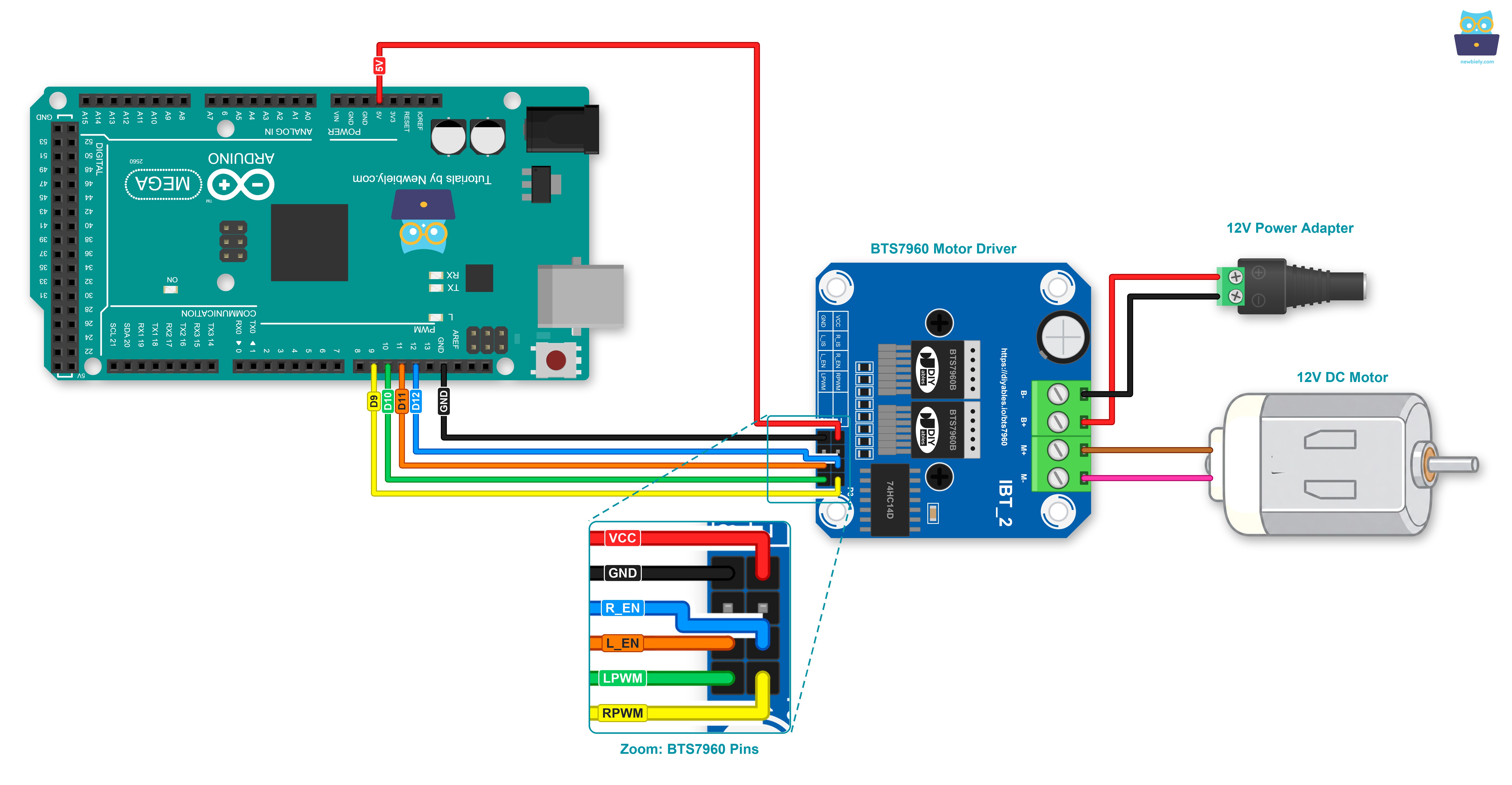
This image is created using Fritzing. Click to enlarge image
| BTS7960 Pin | Arduino Mega 2560 Pin |
|---|---|
| VCC | 5V |
| GND | GND |
| RPWM | D9 (PWM) |
| LPWM | D10 (PWM) |
| R_EN | D12 |
| L_EN | D11 |
| R_IS, L_IS | not used, nothing connected |
| B+ | plus (+) of the 12V supply, from the DC jack |
| B- | minus (-) of the 12V supply, from the DC jack |
| M+, M- | one motor wire each |
Pins 11 and 12 of the Mega can also make PWM, but here they only need to be HIGH or LOW. Mind the order of the two enable wires: the higher pin number (12) belongs to R_EN, and the lower one (11) belongs to L_EN, the same as in the code. The motor current flows only through the screw terminal, so the wires there should be thicker. Thin jumper wires are fine for the control header.
How To Program For BTS7960 Motor Driver
No library is needed. The code uses only analogWrite() and digitalWrite(), which are built into the Arduino core.
- The first step is to name the four Arduino Mega pins that are connected to the control header:
- In the setup() function, all four pins are set as outputs. Both PWM pins start at 0, and only then is the driver switched ON:
- For a lift (forward), LPWM stays at 0 while RPWM gets a speed value between 0 and 255:
- For a lowering move (reverse), the two PWM pins swap their jobs:
- Braking means RPWM = 0 and LPWM = 0, with R_EN and L_EN still HIGH:
- A coast needs the enable pins LOW. Set them back to HIGH before the next move, or the motor will not turn:
Arduino Mega Code for BTS7960 Motor Driver - Lift, Brake, Lower and Coast
The sketch below plays one hoist cycle again and again. The motor turns freely on your desk, but each step has a hoist name:
- LIFT: forward, the PWM value climbs from 0 to 255, stays at 255 for 2 seconds, then falls back to 0
- STOP: a 1-second brake
- LOWER: reverse with a PWM value of 127 (about 50%) for 2 seconds
- REST: 2 seconds of coasting with R_EN and L_EN LOW; after that, both enables go HIGH for the next cycle
Detailed Instructions
- Never used the Arduino Mega before? Start with how to set up the environment for Arduino Mega in the Arduino IDE.
- Make all the connections shown in the wiring diagram. Leave the 12V power adapter unplugged for now.
- Use the USB A/B cable to link the Arduino Mega and your PC.
- Launch the Arduino IDE. In the board menu, pick Arduino Mega or Mega 2560, then the port the Mega is on.
- Start a new sketch, put the code in it, then hit Upload.
- After the IDE says the upload is done, give the motor its power: connect the 12V adapter to mains power.
- Bring up the Serial Monitor and choose 9600 baud. Keep one eye on the motor and one on the messages:
Compare the STOP line with the REST line. Before STOP, the ramp has already slowed the motor down, so the brake is a short, firm pause. REST comes straight after the reverse run, and you can see the shaft keep turning for a short time before it is still. Is the motor turning the "lower" way during the [LIFT] lines? Pull the 12V adapter out, then trade the places of the two motor wires in the M+ and M- terminals. No change to the sketch is needed.
A low PWM value can make the motor sing or buzz a little. Nothing is wrong: the PWM on pins 9 and 10 of the Mega runs at about 490 Hz, and our ears can hear that tone.
Additional Knowledge
BTS7960 vs L298N vs DRV8833
All three are H-bridge boards, yet each one fits a different size of motor:
| BTS7960 | L298N | DRV8833 | |
|---|---|---|---|
| How many DC motors | 1 | 2 | 2 |
| Current | 43A peak (chip limit) | around 2A for each motor | around 1.5A for each motor |
| Voltage drop across the driver | very small | around 2V | small |
| Typical job | hoists, winches, scooters, big gear motors, heavy robots | medium motors | small robots on batteries |
It is evident that a hoist, a winch or any other single high-current motor belongs on the BTS7960. Its motor supply also covers 6V, 12V and 24V systems (5.5V to 27V). For a pair of small motors, the DRV8833 or the L298N does the job with one board for both motors.
Brake, Coast and a Real Hoist
In this tutorial, the motor spins with nothing on it, so coasting is harmless. With a load on a real hoist, it is a different story. When the driver is OFF (coast), the weight of the load can turn the motor backwards and the load drops. Braking slows the drum fast, but it cannot hold a load in the air for a long time. Real hoists add a worm gearbox or a mechanical brake to hold the load, and a limit switch at the top. Add these parts before you lift anything heavy, and never stand under a hanging load.