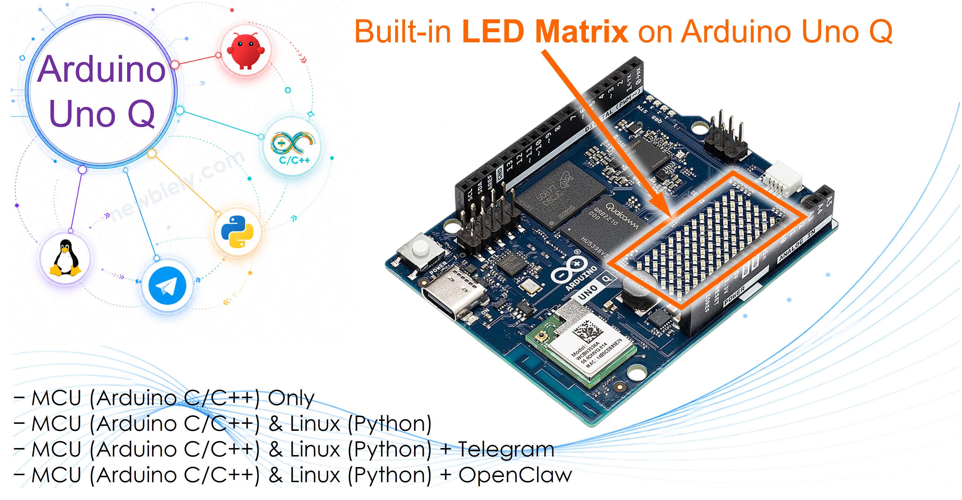
Arduino UNO Q Built-in LED Matrix
The Arduino UNO Q comes with a built-in 8×13 LED matrix on the board — no extra hardware needed! In this tutorial, you will learn how to display digits and characters on it, step by step.
In this tutorial, you will learn:
- What the built-in LED matrix on Arduino UNO Q is and how it works
- How to program the MCU (C/C++ Arduino code) to display digits and characters on the matrix
- How to program both the Linux side (Python) and MCU side (C/C++) to control the matrix remotely via Bridge
- How to send Telegram messages to Arduino UNO Q to display content on the LED matrix
- How to use OpenClaw on Arduino UNO Q with the built-in LED matrix
For using an external LED Matrix module, see the Arduino UNO Q - LED Matrix tutorial.
Hardware Preparation
Or you can buy the following kits:
| 1 | × | DIYables Sensor Kit (18 sensors/displays) |
Additionally, some of these links are for products from our own brand, DIYables .
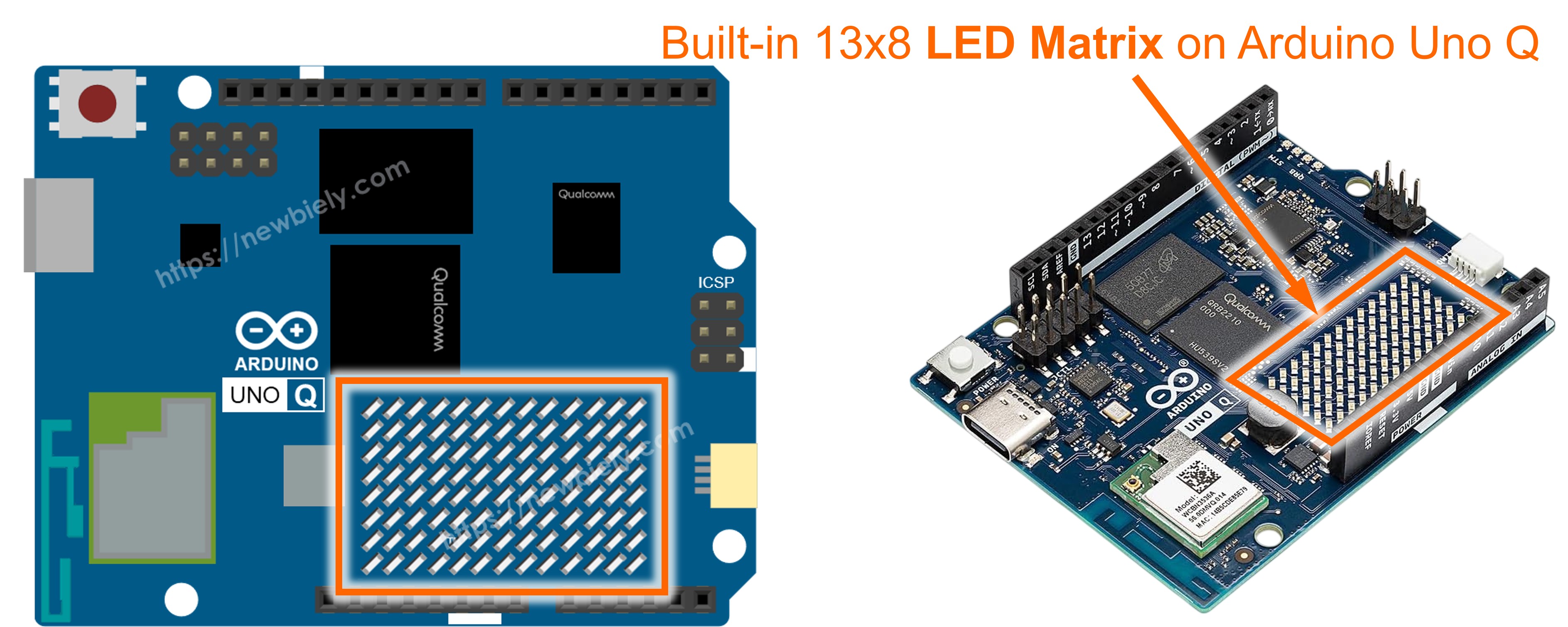
Overview of the Built-in LED Matrix
The Arduino UNO Q includes an onboard 8×13 LED matrix — a grid of 13 columns and 8 rows of LEDs (104 LEDs total). It is controlled directly by the STM32 MCU via the Arduino_LED_Matrix library.
Key facts:
- Size: 13 columns × 8 rows (104 LEDs total)
- No wiring needed: it is soldered directly onto the Arduino UNO Q board
- Controlled by: the STM32 MCU; the Linux MPU cannot access it directly
- Library: Arduino_LED_Matrix — provides frame-based rendering
- Font support: the fonts.h helper file defines bitmaps for digits 0–9 and letters A–Z
How it works:
- A flat frame[104] array holds pixel values (0 = off, 1 = on), indexed as frame[row * 13 + col]
- You call matrix.draw(frame) to push the frame to the physical display
- Characters from fonts.h are drawn into the frame using add_to_frame(char c, int pos), where pos is the starting column (0–12)
- A single 5-pixel-wide character fits at column position 4 for center alignment; two characters fit at positions 0 and 7
MCU Code - Displays digits or characters
The sketch below sequentially displays digits 0–9, then letters A–Z one by one in the center of the LED matrix.
Detailed Instructions
First time with Arduino UNO Q? Follow the Getting Started with Arduino UNO Q tutorial to get your development environment ready before proceeding.
- Connect: Plug the USB-C cable into the Arduino UNO Q — no extra wiring needed.
- Open Arduino App Lab: Launch Arduino App Lab and wait until it detects your Arduino UNO Q — this can take several minutes on first launch.
- Create a new App: Click the Create New App button.

- Give the App a name, for example: BuiltInLedMatrixCharacter
- Click Create to confirm.
- You will see a set of folders and files generated inside your new App.

- Find the sketch/sketch.ino file — this is where you will paste the MCU sketch.
- Also find the sketch/fonts.h file location — you will create a new file with this name.
- Install the library: Click the Add sketch library button (the open book icon with a + sign) in the left sidebar.

- Search for Arduino_RouterBridge created by Arduino and click the Install button.
- Upload: Click the Run button in Arduino App Lab to compile and upload to the STM32.

The LED matrix cycles through digits 0–9, then letters A–Z!
Code Explanation
In the provided code, it is crucial to focus on the add_to_frame(char c, int pos) function. This function accepts two arguments:
- char c: The character to be displayed. Valid values range from 0 to 9 and A to Z.
- int pos: The column position where the character should be displayed. Valid values range from 0 to 12.
MCU Code - Displays two characters simultaneously
The following MCU sketch simultaneously displays two characters on the LED matrix.
Detailed Instructions
- Use the same fonts.h file from the previous section.
- Paste the above sketch into sketch/sketch.ino in your App and click the Run button.
The LED matrix displays two characters simultaneously!
Bridge: Linux + MCU
This section shows how to program both processors of the Arduino UNO Q so the Linux side can control the built-in LED matrix remotely:
- The LED matrix is controlled by the MCU (STM32) — the MCU renders characters onto the physical display
- The MPU cannot access the LED matrix directly — it must send commands to the MCU via Bridge.call()
- The MPU has Wi-Fi — running full Debian Linux, it can connect to the Internet and trigger matrix updates remotely
- Arduino_RouterBridge enables RPC communication between the two processors
- ⚠️ /dev/ttyHS1 (Linux) and Serial1 (MCU) are RESERVED by the router — never open them in user code
In short: MCU renders characters on the LED matrix → MPU sends display commands → MPU can update the matrix from anywhere over the Internet.
MCU Code (Bridge)
Python Code (Bridge)
Detailed Instructions
- Connect: Plug the USB-C cable into the Arduino UNO Q — no extra wiring needed.
- Open Arduino App Lab: Launch Arduino App Lab and wait for the board to be detected.
- Create a new App: Click Create New App, name it BuiltInLedMatrixBridge, then click Create.
- Paste the MCU sketch: Copy the MCU Bridge code above and paste it into sketch/sketch.ino.
- Create fonts.h: Add a fonts.h file in the sketch folder with the same fonts definition as the previous section.
- Paste the Python code: Copy the Python Bridge code above and paste it into the Python file in the App.
- Upload: Click the Run button in Arduino App Lab.
App Lab Console Output
Telegram
Control the built-in LED matrix from anywhere using Telegram — display digits or letters on the matrix from your phone!
MCU sketch: Keep the same MCU sketch from the previous Bridge section.
Python Code (Telegram)
Detailed Instructions
- Replace YOUR_TELEGRAM_BOT_TOKEN with your actual bot token from BotFather.
- Replace YOUR_CHAT_ID with your Telegram chat ID.
- Paste this Python code into your App's Python file (keep the same MCU sketch and fonts.h).
- Click the Run button. Open Telegram and send commands to your bot.
App Lab Console Output

ArduinoBot
OpenClaw Integration
You can adapt the OpenClaw to this tutorial by refering the instruction on Arduino Uno Q - OpenClaw Tutorial
Project Ideas
You can build many creative projects using the built-in LED matrix on Arduino UNO Q:
- Remote Scoreboard: Send score digits to the matrix via Telegram — display the current game score from anywhere
- Notification Indicator: Flash a letter on the matrix when a new Telegram message or sensor alert arrives
- Countdown Timer: Display a countdown from 9 to 0 on the matrix, controlled from Python over Bridge
- Letter-of-the-Day Bot: Schedule a Python script to display a different letter on the matrix each day via a cron job on the Linux MPU
- Two-Character Status Display: Show two-letter status codes on the matrix (e.g., "OK", "HI", "GO") triggered by Telegram commands
Challenge Yourself
Ready to go further with the built-in LED matrix on Arduino UNO Q? Try these challenges:
- Easy: Add a /scroll Telegram command that scrolls a word across the matrix letter by letter, with a configurable delay.
- Medium: Create a /count Telegram command that counts from 0 to 9 on the matrix automatically, with a 500ms delay between each digit.
- Advanced: Build a Telegram-controlled scrolling text marquee — accept a multi-character string and scroll it across the 12-column display one column at a time using frame manipulation.