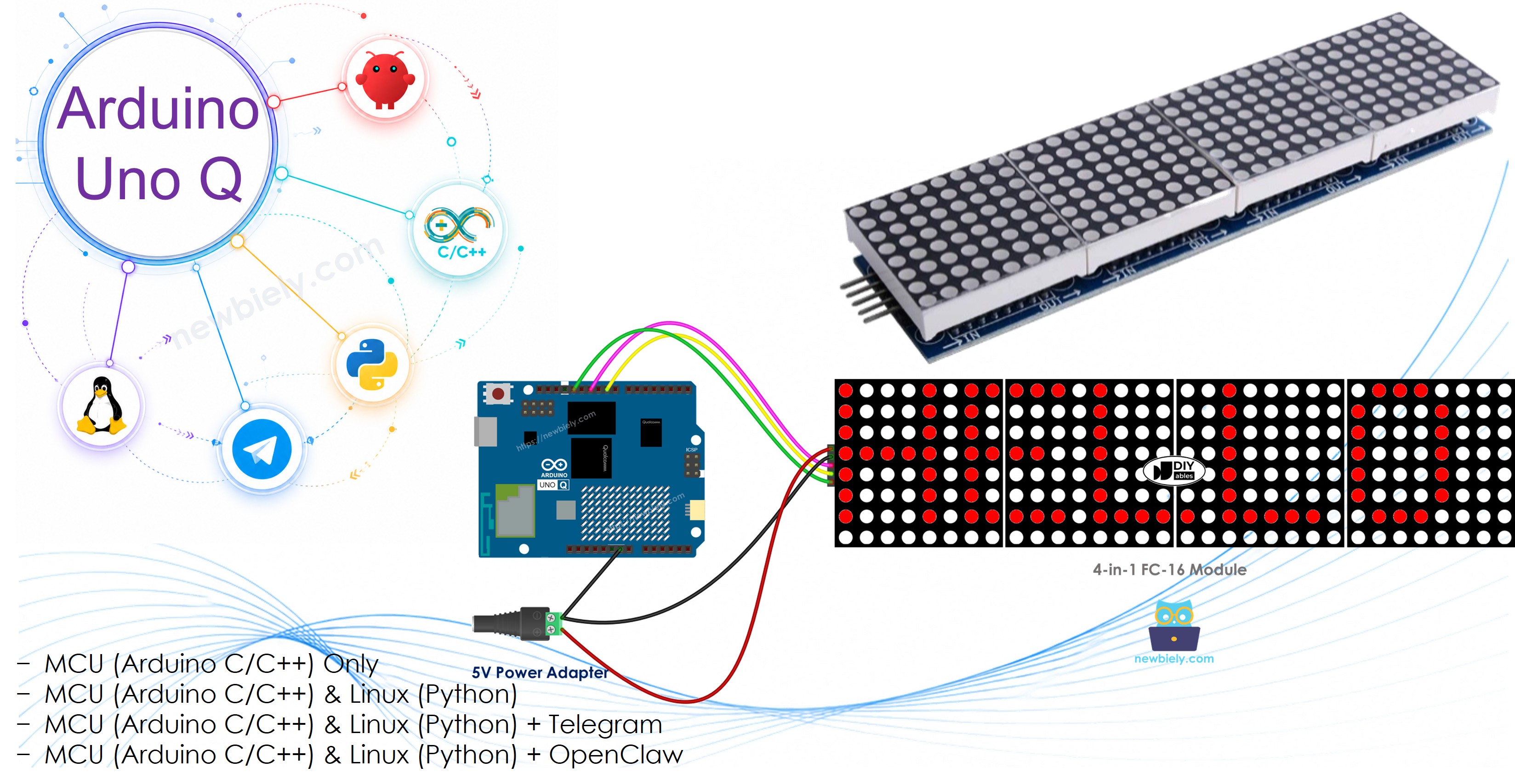
Arduino UNO Q - LED Matrix
Want to display scrolling text or animated messages on a big LED matrix panel with your Arduino UNO Q? This tutorial shows you how — step by step.
In this tutorial, you will learn:
- What an FC-16 MAX7219 LED matrix is and how it works
- How to wire the LED matrix to Arduino UNO Q
- How to program the MCU (C/C++ Arduino code) to display text, numbers, and scrolling messages
- How to program both the Linux side (Python) and MCU side (C/C++) to control the display remotely via Bridge
- How to send Telegram messages to Arduino UNO Q to control the LED matrix
- How to use OpenClaw on Arduino UNO Q with the LED matrix
For the onboard 12×8 LED matrix built into the Arduino UNO Q itself, see the Arduino UNO Q - Built-in LED Matrix tutorial.
Hardware Preparation
Or you can buy the following kits:
| 1 | × | DIYables Sensor Kit (18 sensors/displays) |
Additionally, some of these links are for products from our own brand, DIYables .
Overview of the LED Matrix
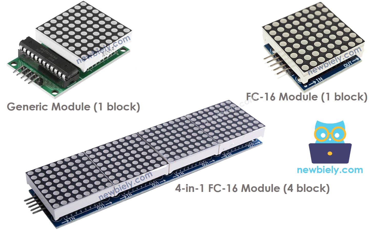
The most common LED matrix used with Arduino is the MAX7219-based LED matrix. Key facts:
- Each block contains an 8×8 grid of 64 LEDs controlled by one MAX7219 chip
- There are two main types of blocks: the generic module and the FC-16 module
- Modules come in single-block (8×8) or multi-block (16×8, 32×8, 64×8) configurations
- Blocks connect in a daisy chain — data passes from one block to the next
- Control is done via SPI: CLK, MOSI (DIN), and one CS pin
- The MD_Parola and MD_MAX72xx libraries handle all the heavy lifting
This tutorial uses a 4-block 32×8 FC-16 LED matrix (4 × 8×8 = 32 columns, 8 rows). The code can be adapted for any size.
Pinout
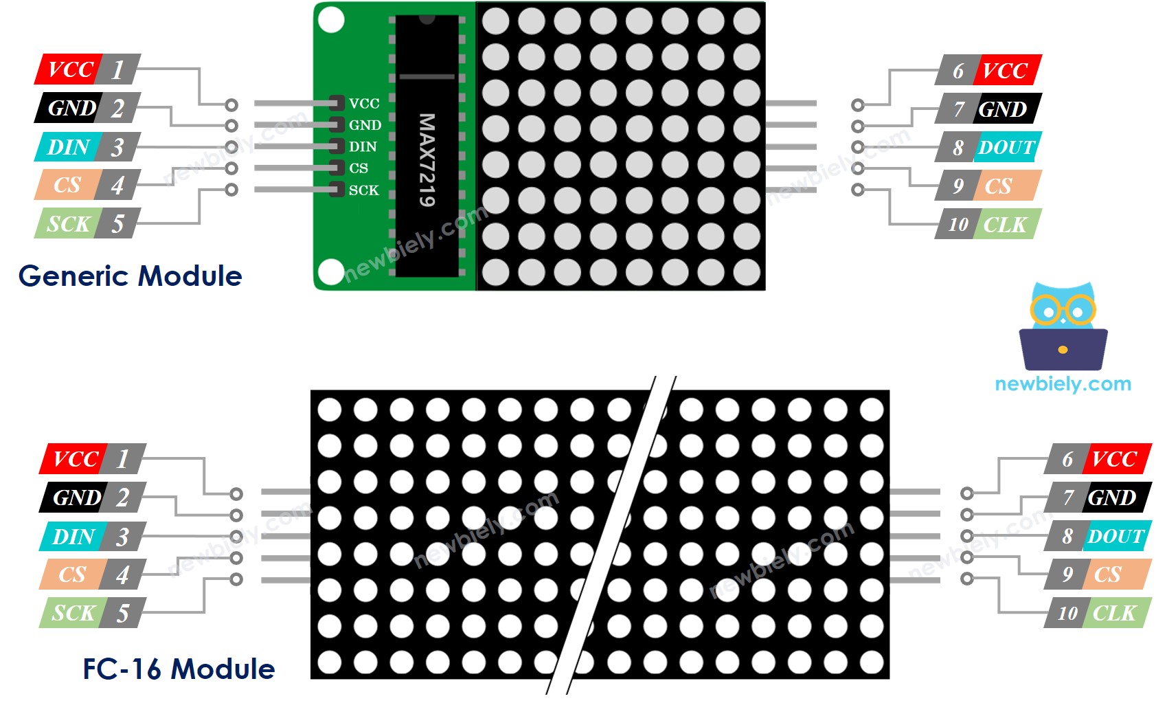
Each block has two sets of pins — one input group (connects to Arduino UNO Q or previous block) and one output group (connects to next block):
- VCC → 5V power supply (external — do not use the 5V pin on Arduino UNO Q for large displays)
- GND → GND
- DIN → SPI MOSI (D11 on Arduino UNO Q MCU)
- CLK → SPI SCK (D13 on Arduino UNO Q MCU)
- CS → any digital pin (D10 in this tutorial)
Wiring Diagram
※ NOTE THAT:
The LED matrix can draw up to 1 A at maximum brightness. Always use an external 5V power supply rather than the Arduino UNO Q's 5V pin. The Arduino UNO Q and the LED matrix can share the same 5V adapter and the same GND.
The Arduino UNO Q MCU connects to the LED matrix using SPI pins: D13 (SCK) and D11 (MOSI). You can use any digital pin for CS (D10 in this tutorial).
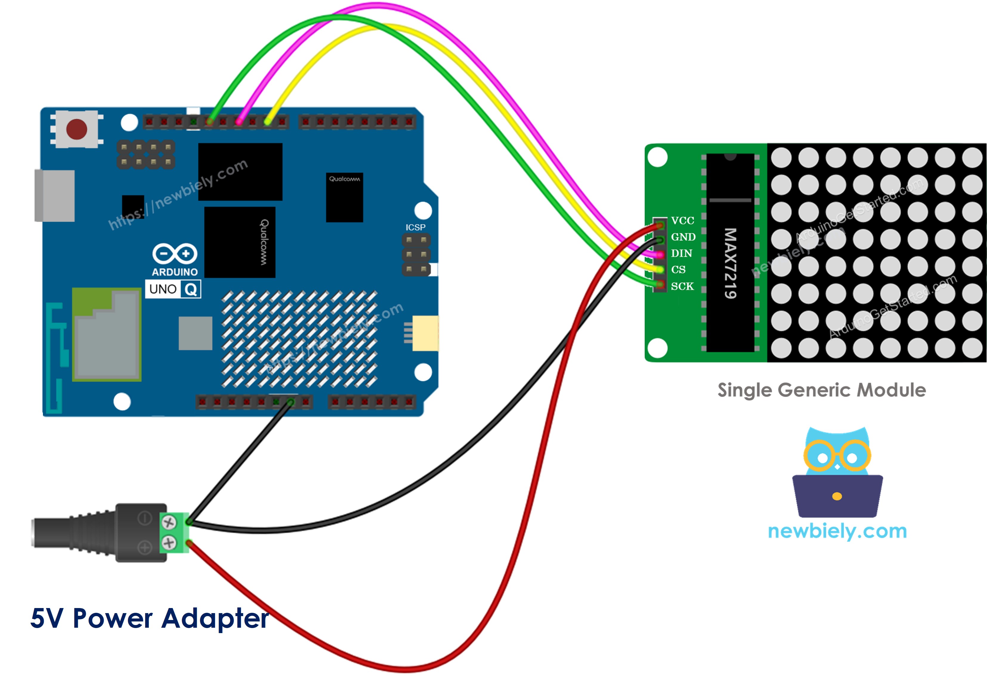
If the LED matrix consists of just one block:
- Connect the group of input pins to the Arduino UNO Q MCU.
- Leave the group of output pins unconnected.
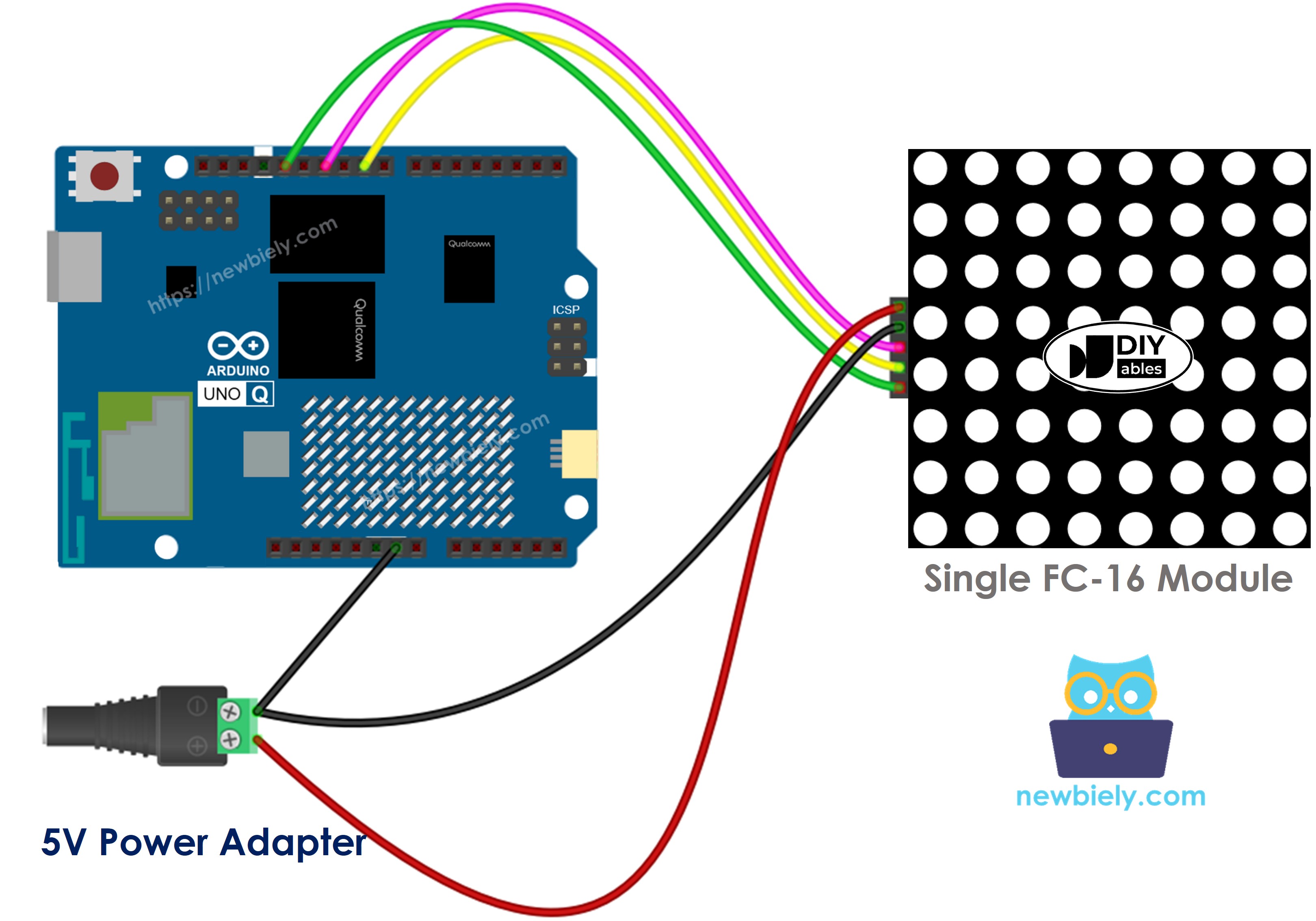
This image is created using Fritzing. Click to enlarge image
This image is created using Fritzing. Click to enlarge image
If the LED matrix comes already assembled into multiple blocks:
- Connect the group of input pins to the Arduino UNO Q MCU.
- Leave the group of output pins unconnected.
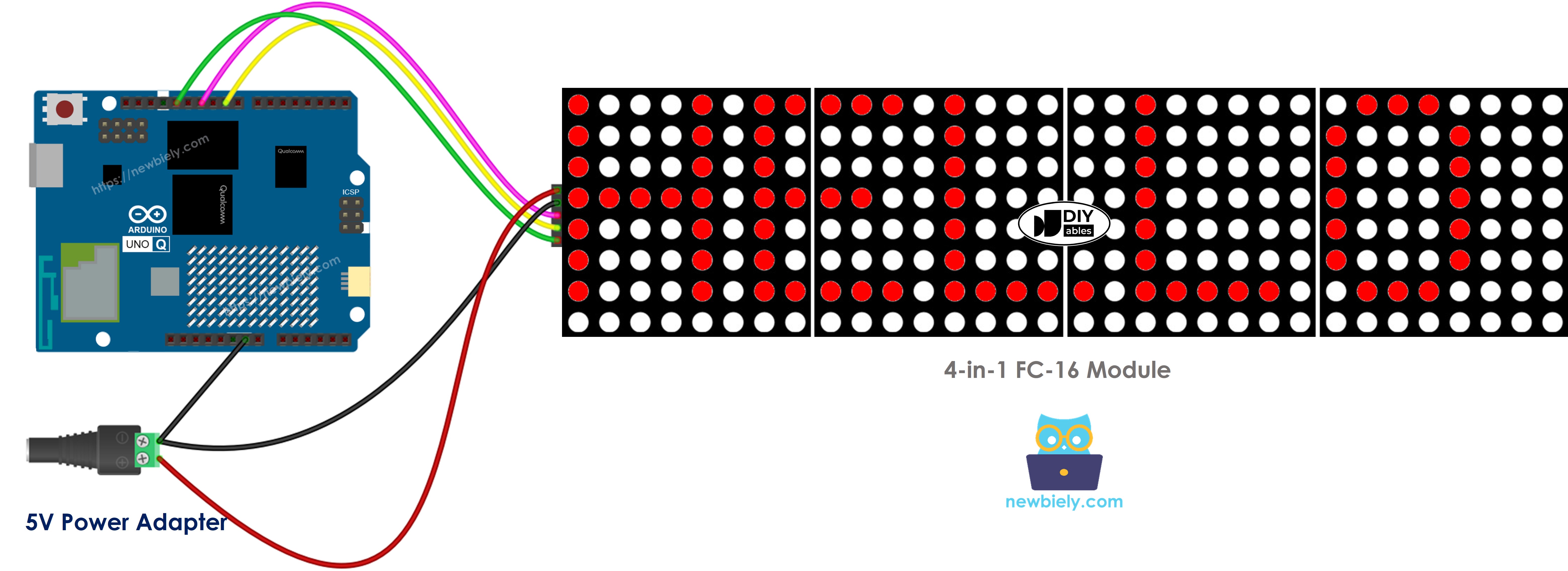
This image is created using Fritzing. Click to enlarge image
If you assemble the LED matrix from several individual blocks:
- Connect the input pin group of the first block to the Arduino UNO Q MCU.
- Connect the output pin group of each block to the input pin group of the next block.
- Leave the output pin group of the last block unconnected.
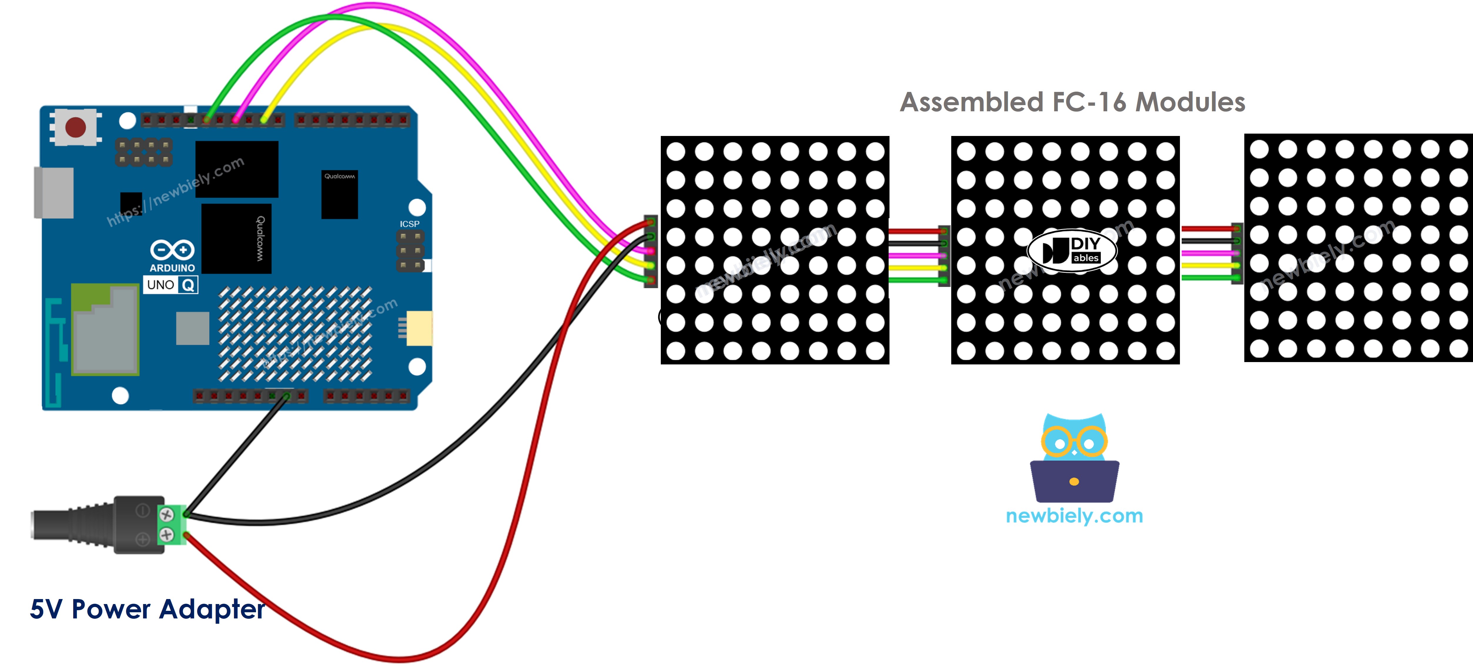
This image is created using Fritzing. Click to enlarge image
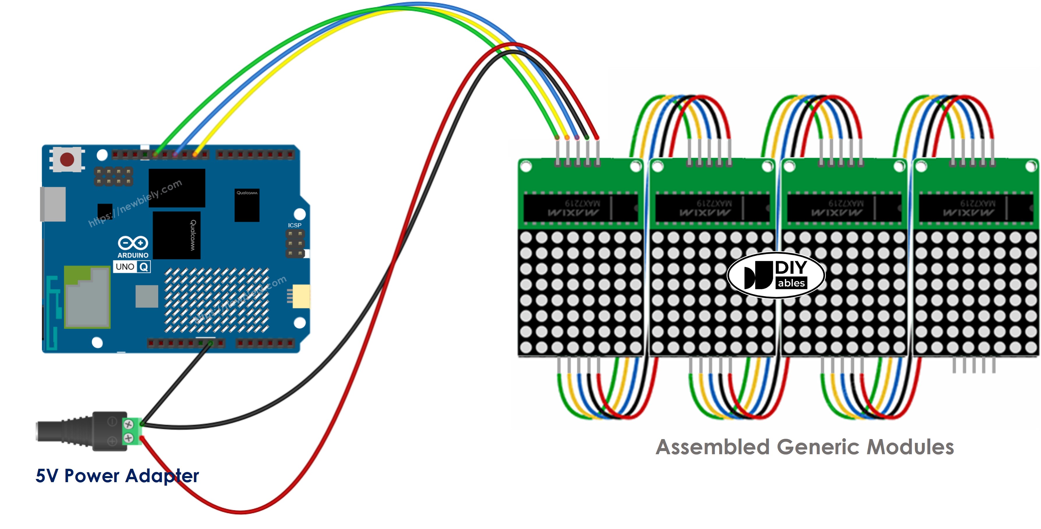
This image is created using Fritzing. Click to enlarge image
| LED Matrix | Arduino UNO Q MCU |
|---|---|
| VCC | External 5V power supply |
| GND | GND (shared with Arduino UNO Q GND) |
| DIN | D11 (MOSI) |
| CLK | D13 (SCK) |
| CS | D10 |
Arduino UNO Q Code
The Arduino UNO Q has two processors working together:
- The STM32 MCU drives the LED matrix directly via SPI using the MD_Parola library
- The Qualcomm MPU runs Debian Linux and handles Wi-Fi, Python, and cloud connectivity
- In this section, only the MCU is programmed — the Linux side stays idle. A later section shows how both processors work together via Bridge.
The sketch below demonstrates static text (left/center/right/inverted), a number display, and a scrolling message:
Detailed Instructions
First time with Arduino UNO Q? Follow the Getting Started with Arduino UNO Q tutorial to get your development environment ready before proceeding.
- Connect: Wire the LED matrix to the Arduino UNO Q MCU as shown in the wiring diagram above. Power the matrix from an external 5V adapter and connect GND to the Arduino UNO Q GND.
- Open Arduino App Lab: Launch Arduino App Lab and wait until it detects your Arduino UNO Q.
- Create a new App: Click the Create New App button.

- Give the App a name, for example: LedMatrix
- Click Create to confirm.

- Find the sketch/sketch.ino file — this is where you will paste the MCU sketch.
- Install the library: Click the Add sketch library button (the open book icon with a + sign) in the left sidebar.

- Search for Arduino_RouterBridge created by Arduino and click the Install button.
- Search for MD_Parola created by majicDesigns and click the Install button.
- Search for MD_MAX72XX created by majicDesigns and click the Install button.
- Upload: Click the Run button in Arduino App Lab to compile and upload to the STM32.

The LED matrix cycles through text alignments, displays a number, and then scrolls "Hello, DIYables!" across the display!
Arduino UNO Q LED Matrix Code – Scrolling Text
When you need to show a long message on a LED matrix display that is too long to fit, you can use the scrolling text effect.
This code demonstrates how to make a message scroll continuously across the LED matrix display.
To see more text effects, go to MD_Parola Library Reference.
Bridge: Linux + MCU
This section shows how to program both processors of the Arduino UNO Q so the Linux side can control the LED matrix remotely:
- The LED matrix is connected to the MCU (STM32) via SPI — the MCU drives the display directly
- The MPU cannot access the LED matrix directly — it must send commands to the MCU via Bridge.call()
- The MPU has Wi-Fi — running full Debian Linux, it can connect to the Internet and trigger display updates remotely
- Arduino_RouterBridge enables RPC communication between the two processors
- ⚠️ /dev/ttyHS1 (Linux) and Serial1 (MCU) are RESERVED by the router — never open them in user code
In short: MCU drives the LED matrix → MPU sends text commands → MPU can update the display from anywhere over the Internet.
MCU Code (Bridge)
Python Code (Bridge)
Detailed Instructions
- Connect: Wire the LED matrix to the Arduino UNO Q as shown in the wiring diagram, with external 5V power.
- Open Arduino App Lab: Launch Arduino App Lab and wait for the board to be detected.
- Create a new App: Click Create New App, name it LedMatrixBridge, then click Create.
- Paste the MCU sketch: Copy the MCU Bridge code above and paste it into sketch/sketch.ino.
- Paste the Python code: Copy the Python Bridge code above and paste it into the Python file in the App.
- Upload: Click the Run button in Arduino App Lab.
App Lab Console Output
Telegram
Control the LED matrix from anywhere using Telegram — display custom messages or numbers on the panel from your phone!
MCU sketch: Keep the same MCU sketch from the previous Bridge section.
Python Code (Telegram)
Detailed Instructions
- Replace YOUR_TELEGRAM_BOT_TOKEN with your actual bot token from BotFather.
- Replace YOUR_CHAT_ID with your Telegram chat ID.
- Paste this Python code into your App's Python file (keep the same MCU sketch).
- Click the Run button. Open Telegram and send commands to your bot.
App Lab Console Output

ArduinoBot
OpenClaw
You can adapt the OpenClaw to this tutorial by refering the instruction on Arduino Uno Q - OpenClaw Tutorial
Project Ideas
You can build many creative projects using the LED matrix with Arduino UNO Q:
- Remote Notice Board: Send custom messages to the LED matrix panel via Telegram — ideal for office displays, shop signs, or event announcements
- Live Score Display: Display sports scores or game results on the matrix, updated in real time from the Linux side via Bridge
- Countdown Timer: Python counts down and updates the matrix display every second until zero
- IoT Weather Display: Fetch weather data on the Linux MPU and scroll the temperature and conditions across the LED matrix automatically
- Telegram Billboard: Allow anyone in a group chat to send a message that gets displayed on the matrix panel via a shared Telegram bot
Challenge Yourself
Ready to go further with the LED matrix on Arduino UNO Q? Try these challenges:
- Easy: Add a /number <value> Telegram command that displays an integer on the LED matrix using ledMatrix.print(int).
- Medium: Add a /scroll <text> Bridge function that starts a scrolling animation — use a background flag in the MCU loop() to call displayAnimate() and displayReset() while scrolling is active.
- Advanced: Build a Telegram-controlled news ticker — accept multiple messages via Telegram and queue them, displaying each in sequence on the matrix as a scrolling marquee.