Raspberry Pi - 2-Channel Relay Module
When we need to control four high-voltage devices such as pumps, fans, actuators, etc., we can utilize multiple relay modules. Alternatively, there is a simpler solution: a 2-channel relay module. This type of module is composed of four relays on a single board.
A 2-channel relay module compared to 2 x 1-channel relay modules:
- Wiring is simpler with the 2-channel relay module.
- The 2-channel relay module requires less space.
- The 2-channel relay module is more cost-effective.
- Programming is the same for both.
Hardware Preparation
Or you can buy the following kits:
| 1 | × | DIYables Sensor Kit (18 sensors/displays) |
Additionally, some of these links are for products from our own brand, DIYables .
Overview of 2-Channel Relay Module
The 2-Channel Relay Module Pinout
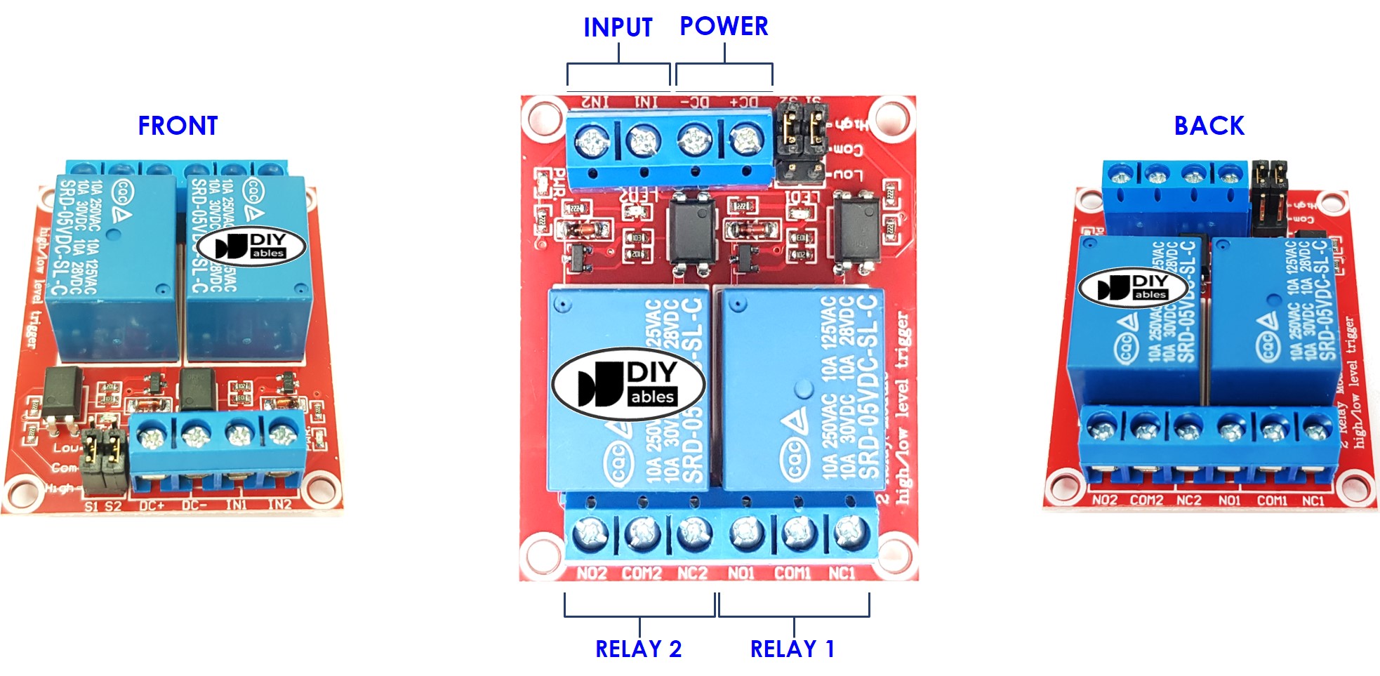
A 2-channel relay module has the following pins:
- Power pins for relay boards
- DC+: connect this pin to 5V pin of power supply
- DC-: connect this pin to the GND pin of the power supply and also to the GND pin of the Raspberry Pi
- Signal pins:
- IN1: this pin receives the control signal from Raspberry Pi to control relay 1 on the module
- IN2: this pin receives the control signal from Raspberry Pi to control relay 2 on the module
- Output pins: NCx (normally closed pin), NOx (normally open pin), COMx (common pin),
- NC1, NO1, COM1: These pins are connected to a high-voltage device that is controlled by relay 1
- NC2, NO2, COM2: These pins are connected to a high-voltage device that is controlled by relay 2
For information on connecting a relay to high-voltage, as well as the differences between normally closed and normally open, please refer to Raspberry Pi - Relay tutorial.
It also has 2 jumpers, allowing one to choose between the low trigger and the high trigger for each relay independently.
Wiring Diagram
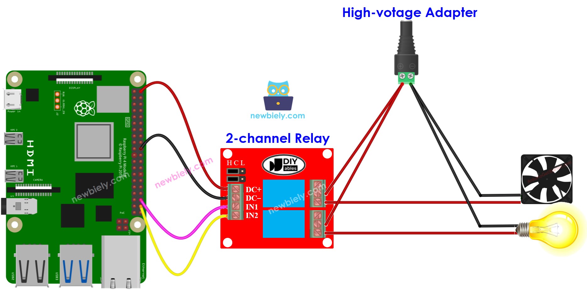
This image is created using Fritzing. Click to enlarge image
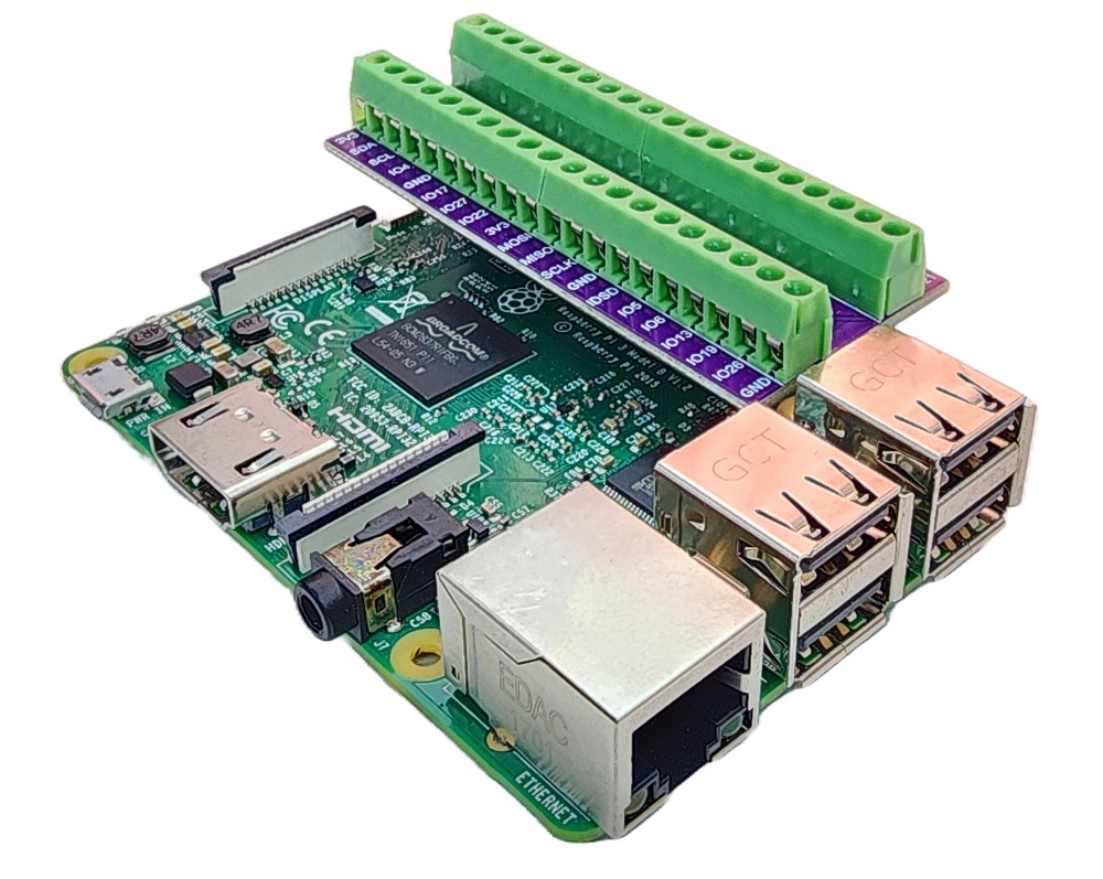
To simplify and organize your wiring setup, we recommend using a Screw Terminal Block Shield for Raspberry Pi. This shield ensures more secure and manageable connections, as shown below:
※ NOTE THAT:
If the four devices controlled by a 2-channel relay module have the same voltage, then a single high-voltage power adapter can be used for all. But, if the voltages are different, then separate high-voltage power adapters must be used.
How To Program For 2-Channel Relay Module
- Sets up the Raspberry Pi pin to digital output mode with the GPIO.setup() function.
- Set the relay's state by utilizing the GPIO.output() function.
Raspberry Pi Code
Detailed Instructions
- Make sure you have Raspbian or any other Raspberry Pi compatible operating system installed on your Pi.
- Make sure your Raspberry Pi is connected to the same local network as your PC.
- Make sure your Raspberry Pi is connected to the internet if you need to install some libraries.
- If this is the first time you use Raspberry Pi, See how to set up the Raspberry Pi
- Connect your PC to the Raspberry Pi via SSH using the built-in SSH client on Linux and macOS or PuTTY on Windows. See to how connect your PC to Raspberry Pi via SSH.
- Make sure you have the RPi.GPIO library installed. If not, install it using the following command:
- Create a Python script file 2_relay_module.py and add the following code:
- Save the file and run the Python script by executing the following command in the terminal:
- Listen for the click sound and LED indicator on the relays.
- Check out the result on the Serial Monitor.
The script runs in an infinite loop continuously until you press Ctrl + C in the terminal.