Raspberry Pi - Water Sensor
This tutorial instructs you how to use Raspberry Pi with the water sensor. In detail, we will learn:
- How to connect Raspberry Pi to the water sensor.
- How to program Raspberry Pi to read the state from the water sensor.
- How to use Raspberry Pi to detect water leakage, rainfall, tank overflow, and measure the water level.
- How to calibrate the water sensor.
Hardware Preparation
Or you can buy the following kits:
| 1 | × | DIYables Sensor Kit (18 sensors/displays) |
Additionally, some of these links are for products from our own brand, DIYables .
Overview of Water Level Sensor
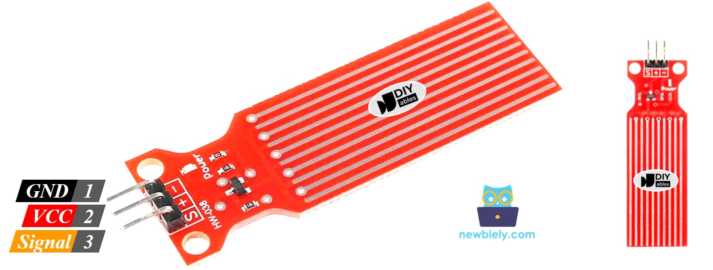
Water Level Sensor Pinout
The water level sensor has 3 pins:
- The S (Signal) pin: This is an analog output that should be connected to one of the analog inputs on your Raspberry Pi.
- The + (VCC) pin: This supplies power for the sensor and it is recommended to use between 3.3V – 5V.
- The - (GND) pin: This is a ground connection.
※ NOTE THAT:
The signal pin of the sensor produces an analog output that is dependent on the voltage provided to the VCC pin.
How Water Level Sensor Works
In short, the output voltage on the signal pin increases as the amount of water the sensor is submerged in increases.
Let's take a closer look.
The sensor has ten exposed copper traces, with five being power traces and the other five being sense traces. These traces are arranged in parallel, with one sense trace between every two power traces. Unless they are bridged by water when submerged, these traces remain unconnected.
The traces act as a variable resistor, similar to a potentiometer, whose resistance is dependent on the water level:
- The resistance is determined by the distance from the top of the sensor to the surface of the water.
- The resistance is inversely proportional to the amount of water present:
- As more water is immersed in the sensor, the conductivity increases and the resistance decreases.
- As less water is immersed in the sensor, the conductivity decreases and the resistance increases.
- The output voltage of the sensor is based on the resistance.
Determining the water level can be done by measuring the voltage.
Wiring Diagram
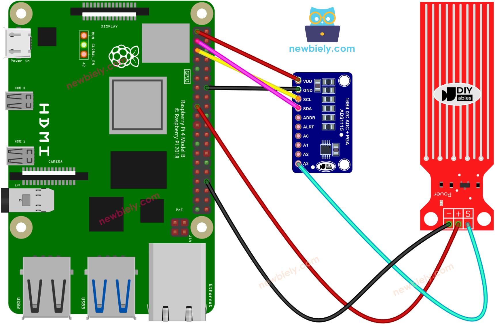
This image is created using Fritzing. Click to enlarge image
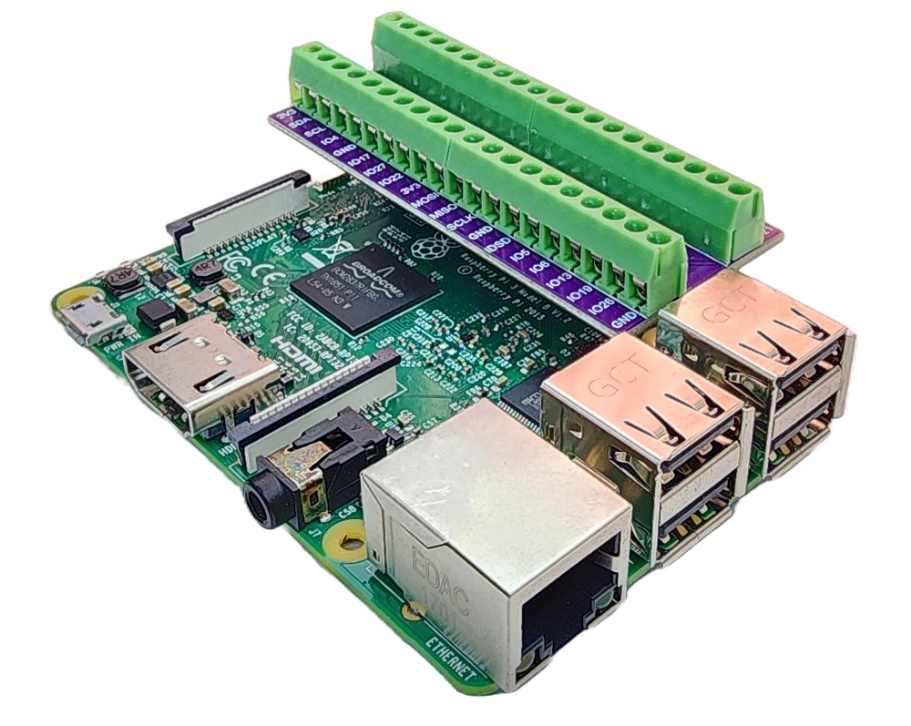
To simplify and organize your wiring setup, we recommend using a Screw Terminal Block Shield for Raspberry Pi. This shield ensures more secure and manageable connections, as shown below:
Raspberry Pi Code - Reading Value from Water Sensor
Detailed Instructions
- Make sure you have Raspbian or any other Raspberry Pi compatible operating system installed on your Pi.
- Make sure your Raspberry Pi is connected to the same local network as your PC.
- Make sure your Raspberry Pi is connected to the internet if you need to install some libraries.
- If this is the first time you use Raspberry Pi, See how to set up the Raspberry Pi
- Connect your PC to the Raspberry Pi via SSH using the built-in SSH client on Linux and macOS or PuTTY on Windows. See to how connect your PC to Raspberry Pi via SSH.
- Make sure you have the RPi.GPIO library installed. If not, install it using the following command:
- Install the Adafruit_ADS1x15 library by running the following commands on your Raspberry Pi terminal:
- Create a Python script file water_sensor.py and add the following code:
- Save the file and run the Python script by executing the following command in the terminal:
- Gently lower the sensor into a glass of water.
- Check the output on the Terminal; it should be 0 when the sensor is not in contact with anything.
The script runs in an infinite loop continuously until you press Ctrl + C in the terminal.
※ NOTE THAT:
The sensor is not meant to be completely submerged; only the exposed traces on the printed circuit board should come into contact with water. Exercise caution when installing it.
How To Detect Water Leakage
To detect water leakage, rainfall, and tank overflow, we only need to compare the reading value with a threshold value that is determined during the calibration portion of this tutorial.
Let us consider a particular instance. If water is detected, Raspberry Pi will activate an LED. For wiring, see how to connect LED to Raspberry Pi
Raspberry Pi Code - Detecting Water Leakage
Detailed Instructions
- Create a Python script file water_sensor_led.py and add the following code:
- Save the file and run the Python script by executing the following command in the terminal:
- Gently lower the sensor into a glass of water.
- Check the output the LED state
Water Level Sensor Calibration
The output of the sensor is not only affected by the water level, but also by the conductivity of the water. Pure water is not conductive, whereas water with minerals and impurities is. The higher the conductivity of the water, the more sensitive the sensor is. Additionally, the output value is also dependent on the voltage supplied to the VCC pin of the sensor.
To ensure accuracy when reading the water sensor, we suggest calibrating the sensor for the specific type of water to be monitored.
Instructions for the calibration:
- Utilize the sketch provided above to read the sensor value.
- Immerse the sensor in the water at the desired level to set the threshold.
- Record the value that the sensor displays in the Terminal.
- Use this value as the threshold to trigger an action.
The test can also be used to discover:
- MIN_ADC_VALUE value, when the sensor is not submerged in the liquid
- MAX_ADC_VALUE value, when the sensor is completely submerged in the liquid
Video Tutorial
Challenge Yourself
- When water leakage is detected:
- Send an email
- Send a SMS message
- Activate a sound alarm