Raspberry Pi - Stepper Motor
This tutorial instructs you how to use Raspberry Pi to control Stepper Motor using L298N Driver. In detail, we will learn:
- How to use Raspberry Pi and L298N driver to control a bipolar stepper motor
- How to program Raspberry Pi to control the position of the stepper motor
- How to program Raspberry Pi to control the speed of the stepper motor
- How to program Raspberry Pi to control the direction of the stepper motor
The tutorial is applicable to all types of bipolar stepper motors with four wires. It will use a NEMA 17 stepper motor as an example.
If you want control another type of stepper motor, please check out this Raspberry Pi - 28BYJ-48 Stepper Motor tutorial.
Hardware Preparation
Or you can buy the following kits:
| 1 | × | DIYables Sensor Kit (18 sensors/displays) |
Additionally, some of these links are for products from our own brand, DIYables .
Overview of Stepper Motor
Two common types of stepper motors exist:
- bipolar: this motor has four wires
- unipolar: this motor has either five or six wires
For a 6-wire unipolar stepper motor, we can utilize four of its six wires and control it as if it were a bipolar stepper motor.
For a 5-wire unipolar stepper motor, refer to Raspberry Pi - control 28BYJ-48 stepper motor using ULN2003 driver.
This tutorial concentrates solely on the bipolar stepper motor.
Bipolar Stepper Motor pinout
The bipolar Stepper Motor has four pins and the names of these pins vary depending on the manufacturer. The following table displays some of the more common names for the pins:
| PIN NO | Naming 1 | Naming 2 | Naming 3 |
|---|---|---|---|
| 1 | A+ | A | A |
| 2 | A- | A | C |
| 3 | B+ | B | B |
| 4 | B- | B | D |
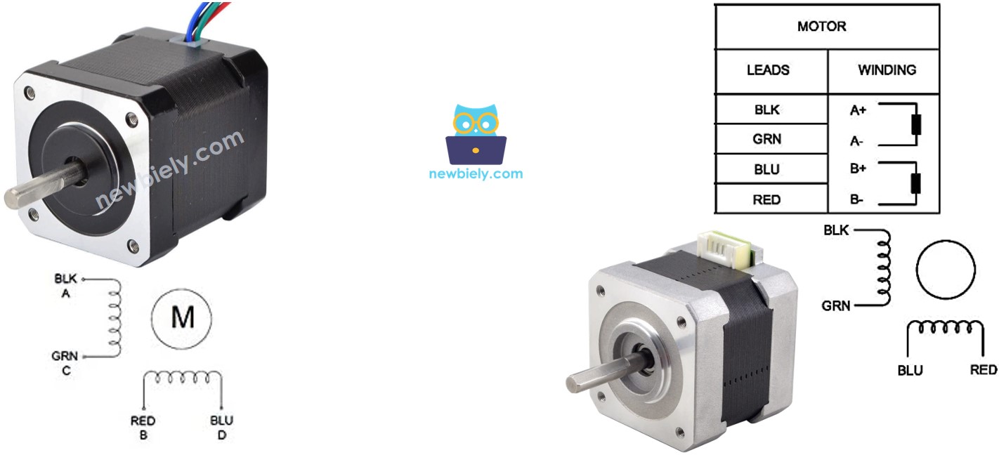
The arrangement of pins, the labelling of wires, and their colours may differ between manufacturers. To determine the connection between the wire colour and its name, you must consult the datasheet or manual. The image above also displays the details of two different motors with different wire labelling and colours.
Steps per Revolution
The specification of the motor states the DEG_PER_STEP. Depending on the control technique, STEP_PER_REVOLUTION can be determined using the following table:
| Control method | Steps per Revolution | Real degree per step |
|---|---|---|
| Full-step | STEP_PER_REVOLUTION = 360 / DEG_PER_STEP | DEG_PER_STEP |
| Half-step | STEP_PER_REVOLUTION = (360 / DEG_PER_STEP) * 2 | DEG_PER_STEP / 2 |
| Micro-step (1/n) | STEP_PER_REVOLUTION = (360 / DEG_PER_STEP) * n | DEG_PER_STEP / n |
For instance, if the motor's data sheet states a 1.8 degree/step:
| Control method | Steps per Revolution | Real degree per step |
|---|---|---|
| Full-step | 200 steps/revolution | 1.8° |
| Half-step | 400 steps/revolution | 0.9° |
| Micro-step (1/n) | (200 * n) steps/revolution | (1.8 / n)° |
How to control a stepper motor using Raspberry Pi
Raspberry Pi can generate signals to control the stepper motor, however, these signals are not of sufficient voltage and/or current to meet the stepper motor's requirements. Consequently, a hardware driver is necessary between Raspberry Pi and the stepper motor. This driver serves two purposes:
- To amplify the control signals from Raspberry Pi in terms of current and voltage
- To protect Raspberry Pi from the high current and voltage used to power the stepper motor.
There are numerous hardware drivers that can be utilized to manage stepper motors. One of the most commonly used hardware drivers for controlling stepper motors is the L298N Driver.
Overview of L298N Driver
A L298N Driver can be used to control two DC motors or a stepper motor. In this guide, we will discover how to utilize it to regulate the stepper motor.
L298N Driver Pinout
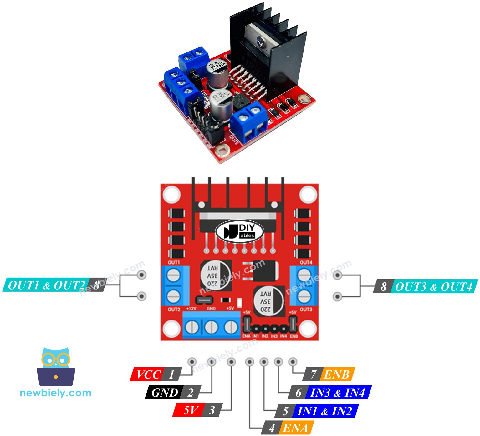
The L298N Driver has 11 pins and three jumpers:
- VCC pin: This supplies power for the motor and can be anywhere between 5 to 35V.
- GND pin: This is a common ground pin, which needs to be connected to GND (0V).
- 5V pin: This supplies power for the L298N module and can be supplied by 5V from Raspberry Pi.
- IN1, IN2, IN3, IN4 pins: These are connected to Raspberry Pi's pins to receive the control signal to control the stepper motor.
- OUT1, OUT2, OUT3, OUT4 pins: These are connected to the stepper motor.
- ENA, ENB jumpers: These are used to enable the stepper motor and both the ENA & ENB jumpers need to be in place.
- 5V-EN jumper: If this is kept in place, the power for the L298N module is got from VCC and nothing needs to be connected to the 5V pin. If the 5V-EN jumper is removed, power must be supplied to the L298N module via a 5V pin.
The L298N driver has two input powers:
- One for the stepper motor (VCC and GND pins): ranging from 5 to 35V.
- One for the module's internal operation (5V and GND pins): from 5 to 7V. If the 5V-EN jumper is kept in place, this pin does not need to be connected.
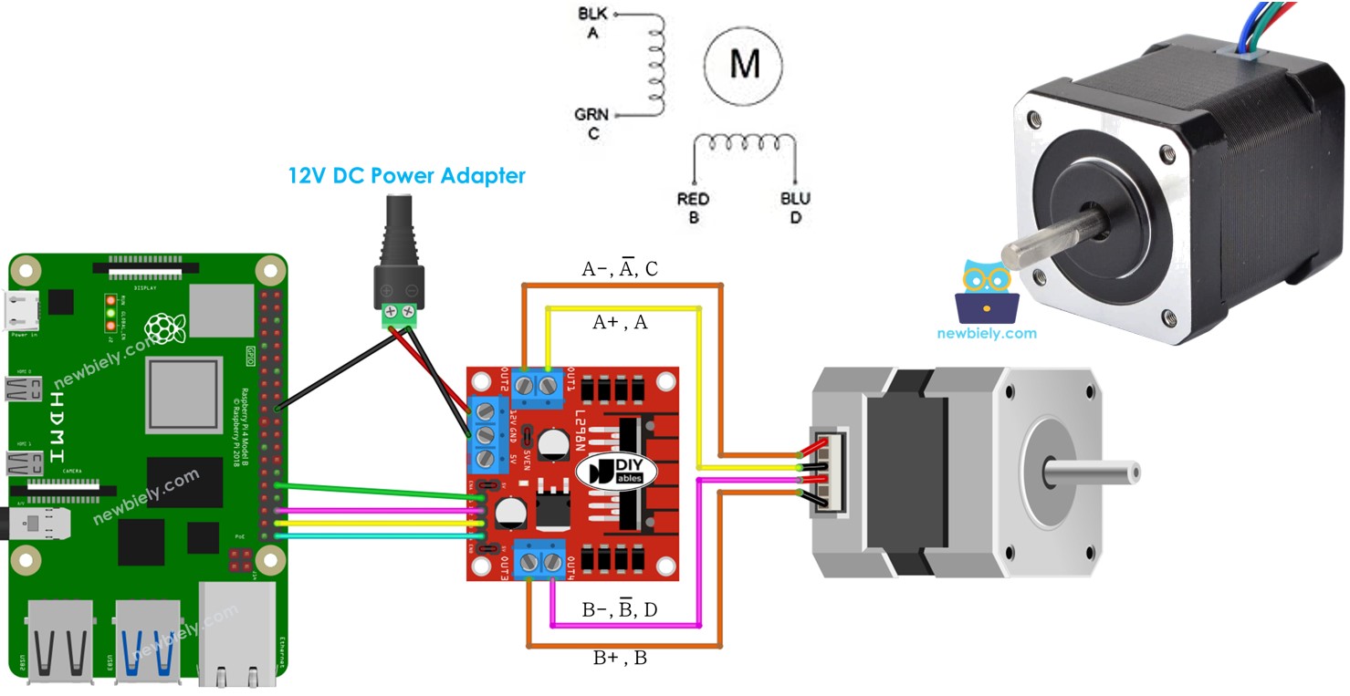
Wiring Diagram
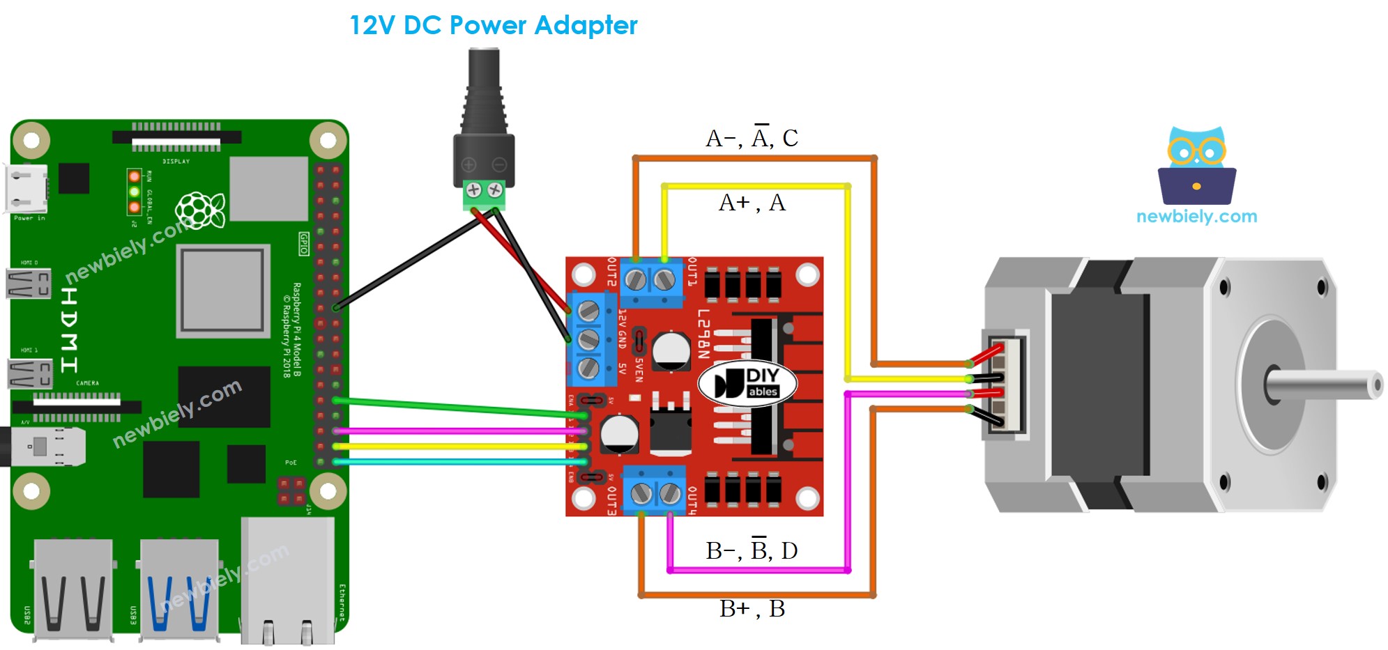
This image is created using Fritzing. Click to enlarge image
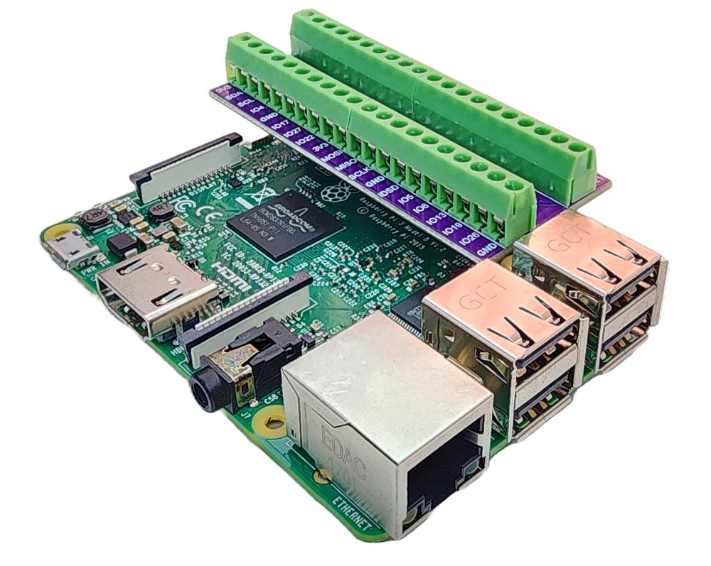
To simplify and organize your wiring setup, we recommend using a Screw Terminal Block Shield for Raspberry Pi. This shield ensures more secure and manageable connections, as shown below:
※ NOTE THAT:
- Keep the three jumpers on the L298N module in place if the motor's power supply is 12V or less.
- The pins on stepper motors may differ between manufacturers. Refer to the table below for the correct wiring.
Wiring table between Raspberry Pi and L298N Driver
| Raspberry Pi pins | L298N pins |
|---|---|
| 12 | IN1 |
| 16 | IN2 |
| 20 | IN3 |
| 21 | IN4 |
Wiring table between L298N Driver and Stepper motor
Important!: Do not pay attention to the order of the wires in the stepper motor on the wiring diagram shown above. It is just an illustration. The pin arrangement on stepper motors can be different depending on the manufacturer. Make sure that your wiring follows the table below.
| L298N pins | Stepper motor pins | Or | Or |
|---|---|---|---|
| OUT1 | A+ | A | A |
| OUT2 | A- | A | C |
| OUT3 | B+ | B | B |
| OUT4 | B- | B | D |
Prior to purchasing a stepper motor, we suggest that you review the datasheet, specification, or manual for the stepper motor. Ensure that it includes the correlation between the pin's color and name. For instance, this stepper motor has the following mapping as shown in the image below:
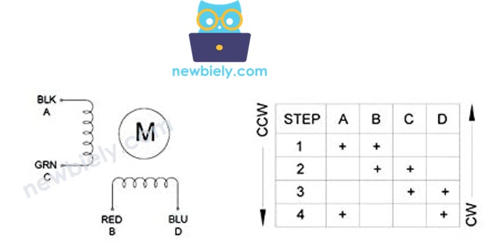
In view of the mapping, the wiring table is as follows:
| L298N pins | stepper motor pins | wire color |
|---|---|---|
| OUT1 | A | black wire |
| OUT2 | C | green wire |
| OUT3 | B | red wire |
| OUT4 | D | blue wire |
※ NOTE THAT:
In the wiring tables between the stepper motor and L298N Driver, there are more ways to do the wiring. We can swap OUT1 with OUT2, OUT3 with OUT4. However, if we do this, the motors' rotation direction may be altered (from clockwise to anticlockwise, and vice versa).
Raspberry Pi Code - Stepper Motor Code
The following code:
- Makes the motor turn one revolution in a clockwise direction
- Pauses the motor for 5 seconds
- Causes the motor to rotate one revolution in an anticlockwise direction
- Halts the motor for 5 seconds
- Repeats the process endlessly
Detailed Instructions
- Make sure you have Raspbian or any other Raspberry Pi compatible operating system installed on your Pi.
- Make sure your Raspberry Pi is connected to the same local network as your PC.
- Make sure your Raspberry Pi is connected to the internet if you need to install some libraries.
- If this is the first time you use Raspberry Pi, See how to set up the Raspberry Pi
- Connect your PC to the Raspberry Pi via SSH using the built-in SSH client on Linux and macOS or PuTTY on Windows. See to how connect your PC to Raspberry Pi via SSH.
- Make sure you have the RPi.GPIO library installed. If not, install it using the following command:
- Create a Python script file stepper.py and add the following code:
- Save the file and run the Python script by executing the following command in the terminal:
The script runs in an infinite loop continuously until you press Ctrl + C in the terminal.
By changing the value of delay variable in the code, you can change the speed of the stepper motor.
You will observe the following:
- The stepper motor will rotate one revolution in a clockwise direction.
- The stepper motor will pause for 5 seconds.
- The stepper motor will then rotate one revolution in an anticlockwise direction.
- The stepper motor will pause for another 5 seconds.
- This process will be repeated.
Code Explanation
Check out the line-by-line explanation contained in the comments of the source code!