Raspberry Pi - LDR Module
The LDR light sensor module can figure out how much light is around it. It has two outputs: a digital output that can be either low or high, and an analog output.
This tutorial instructs you how to use an Raspberry Pi and an LDR light sensor module to find out the amount of light in an area. We will cover the following steps:
- Connecting the LDR light sensor module to an Raspberry Pi.
- Programming the Raspberry Pi to read the state of the LDR light sensor module.
- Programming the Raspberry Pi to detect light.
Later on, you can change the code to turn on an LED or a light bulb (using a relay) when it detects light.
If you prefer a light sensor in its raw form, I suggest exploring the tutorial on the Raspberry Pi - Light Sensor.
Hardware Preparation
Or you can buy the following kits:
| 1 | × | DIYables Sensor Kit (18 sensors/displays) |
Additionally, some of these links are for products from our own brand, DIYables .
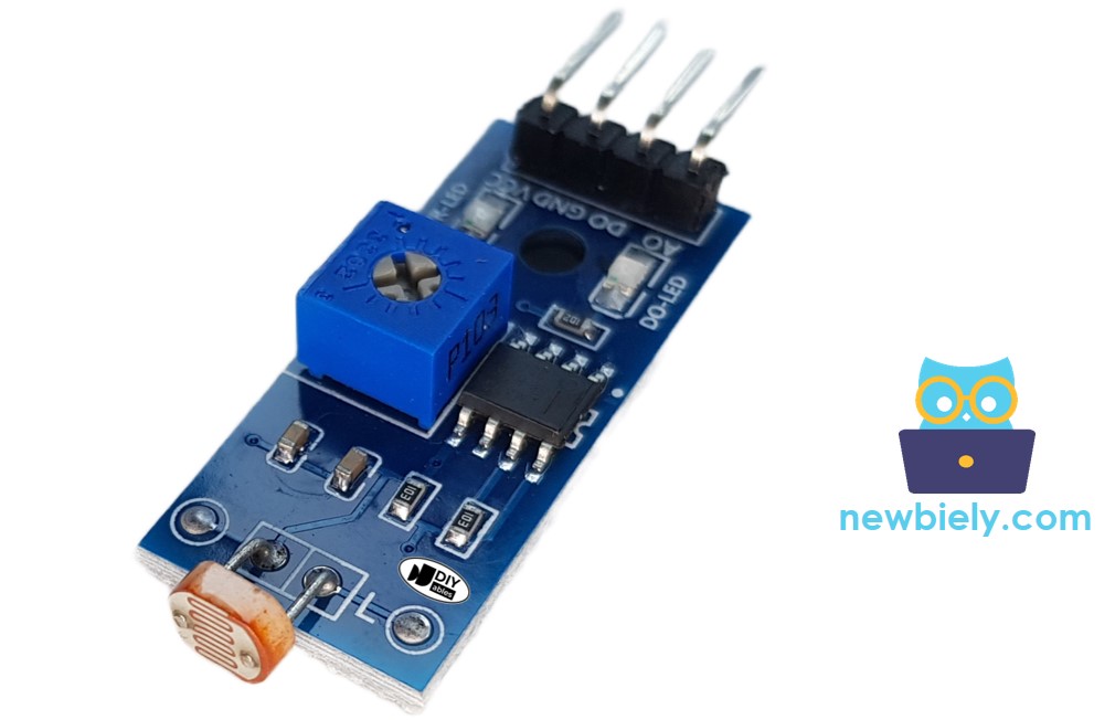
Overview of LDR Light Sensor Module
The LDR light sensor module can be used to find out if there is light or measure how much light is present in the surroundings. It has two options: a digital output pin and an analog output pin.
Pinout
The LDR light sensor module has four pins with different functions:
- VCC pin: Connect it to a power source (between 3.3V to 5V).
- GND pin: Connect it to the ground (0V).
- DO pin: This is a digital output pin. It goes HIGH when it's dark and LOW when it's light. You can adjust the threshold between darkness and lightness using a built-in potentiometer.
- AO pin: This is an analog output pin. The output value decreases as the light gets brighter and increases as the light gets darker.
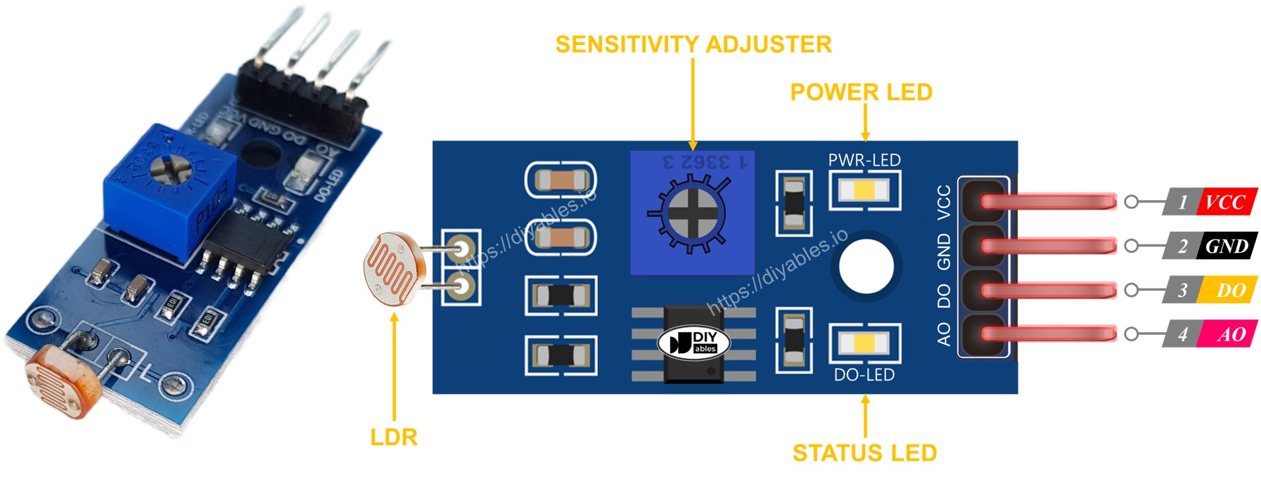
Additionally, the LDR light sensor module has two LED indicators:
- The PWR-LED indicator shows the power status.
- The DO-LED indicator shows the state of light on the DO pin. It is illuminated when there is light and turned off when it is dark.
How It Works
Regarding the DO pin:
- The LDR light sensor module has a built-in potentiometer that allows you to adjust the sensitivity or threshold for detecting light.
- When the surrounding light intensity is higher than the set threshold (considered as light), the output pin of the sensor is set to LOW, and the DO-LED indicator turns on.
- When the surrounding light intensity is lower than the set threshold (considered as dark), the output pin of the sensor is set to HIGH, and the DO-LED indicator turns off.
Regarding the AO pin:
- The value read from the AO pin decreases as the surrounding light intensity increases (considered as light).
- The value read from the AO pin increases as the surrounding light intensity decreases (considered as dark).
It's important to note that adjusting the potentiometer does not affect the value read from the AO pin.
Wiring Diagram
Since the light sensor module has two outputs, you can choose to use one or both of them, depending on what you need.
- The wiring diagram between Raspberry Pi and the LDR light sensor module.
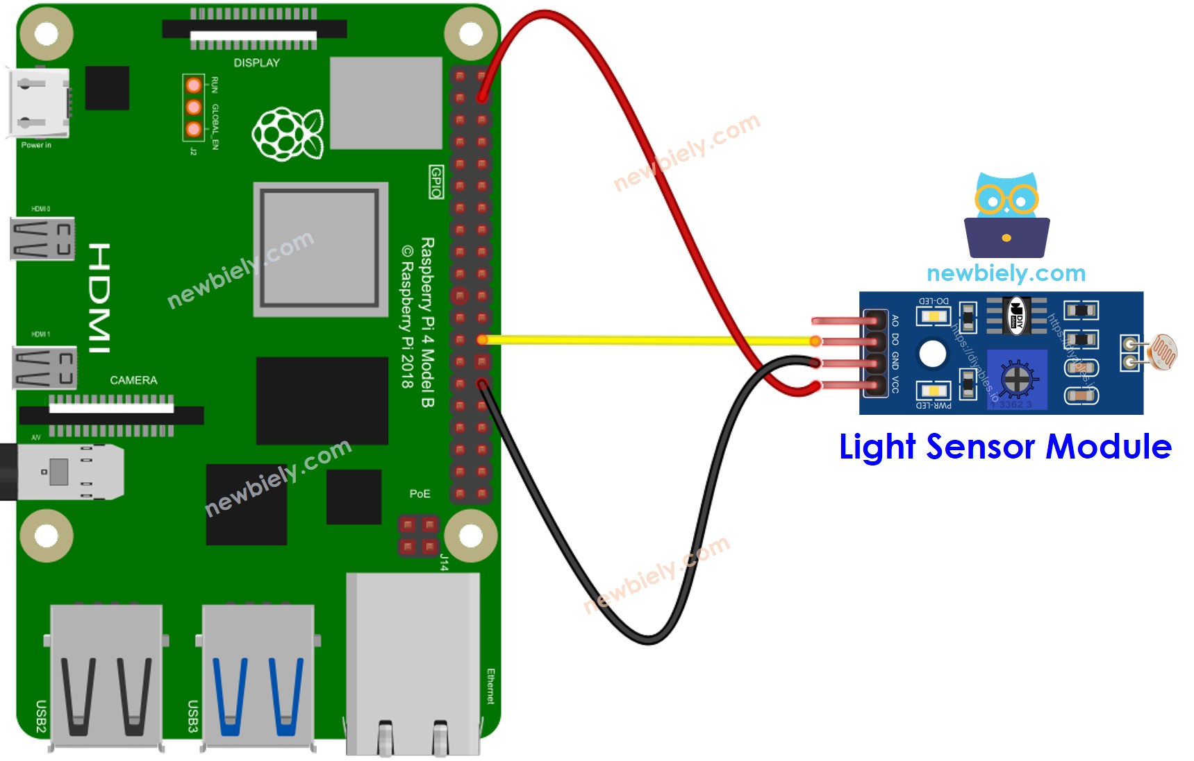
This image is created using Fritzing. Click to enlarge image
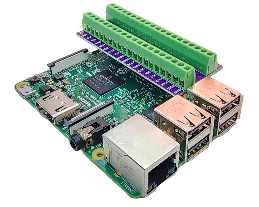
To simplify and organize your wiring setup, we recommend using a Screw Terminal Block Shield for Raspberry Pi. This shield ensures more secure and manageable connections, as shown below:
NOTE THAT:
- The Raspberry Pi lacks built-in analog input pins, so the AO pin can remain unconnected. To read analog values from the module, an external ADC module is required. For more information, refer to How to use Raspberry Pi with ADC module
Raspberry Pi Code - Read value from DO pin
Detailed Instructions
- Make sure you have Raspbian or any other Raspberry Pi compatible operating system installed on your Pi.
- Make sure your Raspberry Pi is connected to the same local network as your PC.
- Make sure your Raspberry Pi is connected to the internet if you need to install some libraries.
- If this is the first time you use Raspberry Pi, See how to set up the Raspberry Pi
- Connect your PC to the Raspberry Pi via SSH using the built-in SSH client on Linux and macOS or PuTTY on Windows. See to how connect your PC to Raspberry Pi via SSH.
- Make sure you have the RPi.GPIO library installed. If not, install it using the following command:
- Create a Python script file ldr_module.py and add the following code:
- Save the file and run the Python script by executing the following command in the terminal:
- Cover and uncover the LDR light sensor module by your hand or something
- See the result on the Terminal.
The script runs in an infinite loop continuously until you press Ctrl + C in the terminal.
If you observe that the LED status remains constantly on or off, even when there is light, you have the option to adjust the potentiometer. This adjustment allows you to finely tune the light sensitivity of the sensor.
Additionally, it is possible to modify the code to activate an LED or a light when light is detected, or even to enable the rotation of a servo motor. Detailed information and step-by-step instructions can be found in the tutorials provided at the end of this guide.
Raspberry Pi Code - Detecting the Light
Let's modify the above code to detect the light state change.
Detailed Instructions
- Create a Python script file ldr_module.py and add the following code:
- Save the file and run the Python script by executing the following command in the terminal:
- Cover and uncover the LDR light sensor module by your hand or something
- See the result on the Terminal.
Raspberry Pi Code - Read value from AO pin
To read the value from the AO pin, you need to use ADS1115 ADC Module since Raspberry Pi does not have any ADC pin. See how to use ADS1115 ADC Module with Raspberry Pi