Raspberry Pi - Door Sensor - LED
This tutorial instructs you how to use the Raspberry Pi and door sensor to control the LED. We will learn two different applications:
Application 1 - LED is on when door is open and LED is off when door is closed. The LED state is synchronized with the door sensor's state. In detail:
- Raspberry Pi turns on the LED when the door is opened.
- Raspberry Pi turns off the LED when the door is closed.
Application 2 - The LED state is toggled each time the door is opened. More specifically:
- If Raspberry Pi detects that the door has been opened (the sensor state changes from LOW to HIGH), it will turn ON the LED if it's currently OFF, or turn OFF the LED if it's currently ON.
- Closing the door sensor does not affect to the LED state.
Hardware Preparation
Or you can buy the following kits:
| 1 | × | DIYables Sensor Kit (18 sensors/displays) |
Additionally, some of these links are for products from our own brand, DIYables .
Buy Note: Use the LED Module for easier wiring. It includes an integrated resistor.
Overview of LED and Door Sensor
If you are unfamiliar with LED and door sensor (including pinout, operation, and programming), the following tutorials can help:
Wiring Diagram
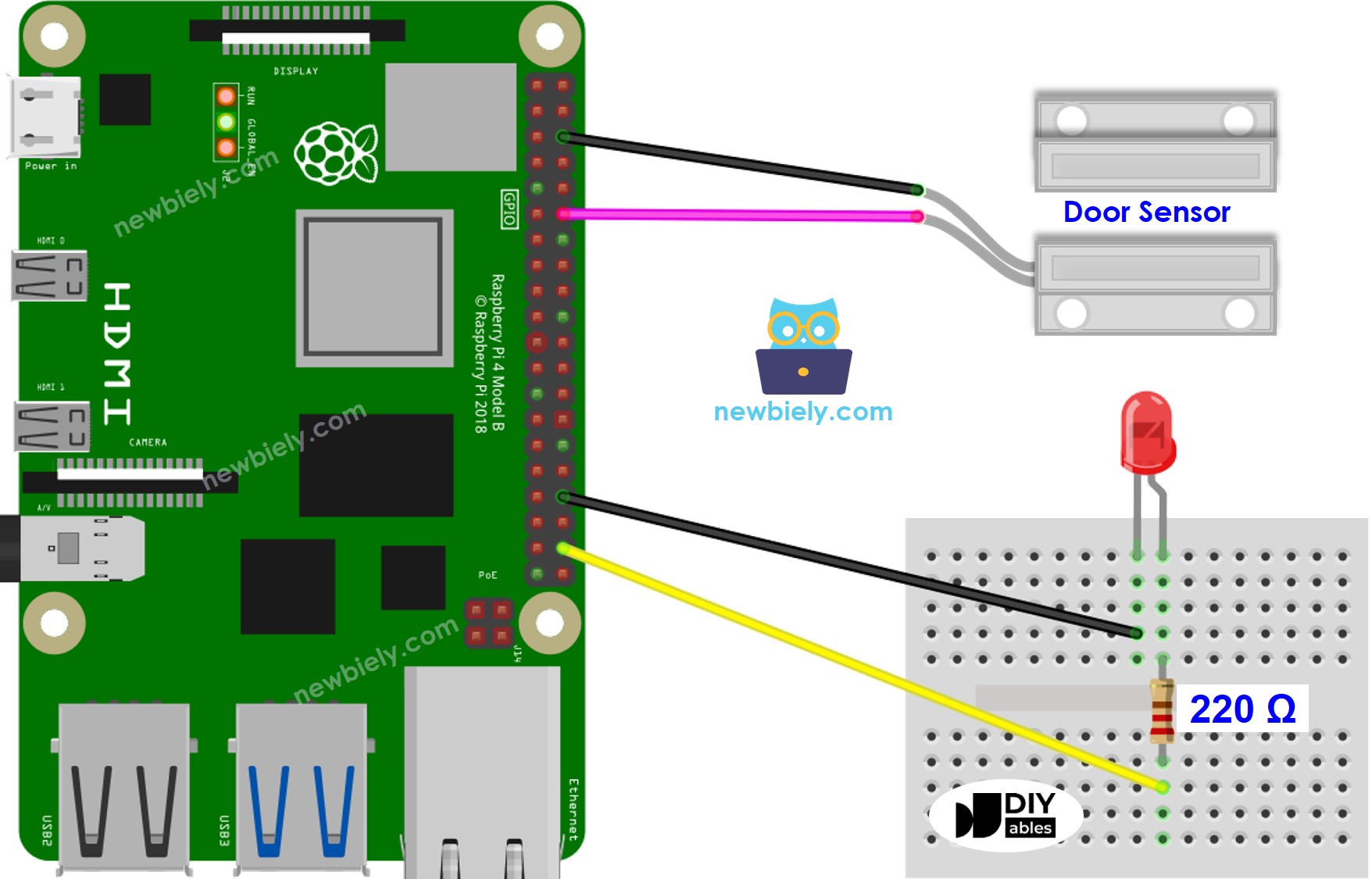
This image is created using Fritzing. Click to enlarge image
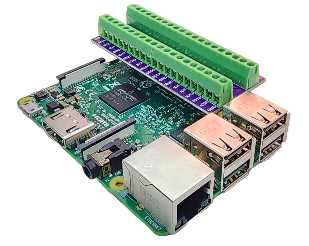
To simplify and organize your wiring setup, we recommend using a Screw Terminal Block Shield for Raspberry Pi. This shield ensures more secure and manageable connections, as shown below:
Application 1 - The LED state is in sync with the door sensor state
Detailed Instructions
- Make sure you have Raspbian or any other Raspberry Pi compatible operating system installed on your Pi.
- Make sure your Raspberry Pi is connected to the same local network as your PC.
- Make sure your Raspberry Pi is connected to the internet if you need to install some libraries.
- If this is the first time you use Raspberry Pi, See how to set up the Raspberry Pi
- Connect your PC to the Raspberry Pi via SSH using the built-in SSH client on Linux and macOS or PuTTY on Windows. See to how connect your PC to Raspberry Pi via SSH.
- Make sure you have the RPi.GPIO library installed. If not, install it using the following command:
- Create a Python script file door_sensor_led.py and add the following code:
- Save the file and run the Python script by executing the following command in the terminal:
- Open and close the door
- Check out the change in the LED's state. You will see that the LED state is in sync with the door sensor state.
The script runs in an infinite loop continuously until you press Ctrl + C in the terminal.
Code Explanation
Check out the line-by-line explanation contained in the comments of the source code!
Application 2 - Door Sensor toggles LED
Detailed Instructions
- Create a Python script file door_sensor_toggle_led.py and add the following code:
- Save the file and run the Python script by executing the following command in the terminal:
The script runs in an infinite loop continuously until you press Ctrl + C in the terminal.
- Open and close the door several times.
- Check out the change in the LED's state. You will see that the LED state is toggled once each time the door is closed.