Raspberry Pi - RFID - Servo Motor
This tutorial instructs you how to use a Raspberry Pi and an RFID NFC RC522 module to control a servo motor. The process works as follows:
- When an authorized tag is tapped, the Raspberry Pi will rotate the servo motor to 90°
- If the same authorized tag is tapped again, the Raspberry Pi will rotate the servo motor back to 0°
- This cycle will repeat continuously
This can be used to secure a cabinet, drawer, door, or to open and close a pet feeder...
Hardware Preparation
Or you can buy the following kits:
| 1 | × | DIYables Sensor Kit (18 sensors/displays) |
Additionally, some of these links are for products from our own brand, DIYables .
Buy Note: For controlling multiple servo motors, use the PCA9685 16 Channel PWM Servo Driver Module to save MCU pins and simplify wiring.
Overview of RFID/NFC RC522 Module and Servo Motor
If you are unfamiliar with the RFID/NFC RC522 Module and Servo Motor (including pinout, how it works, and how to program), the following tutorials can provide more information:
- Raspberry Pi - RFID/NFC RC522 tutorial
- Raspberry Pi - Servo Motor tutorial
How It Works
- The UIDs of certain RFID/NFC tags are programmed into the Raspberry Pi code.
- When the user taps an RFID/NFC tag onto the RFID/NFC reader, the reader reads the UID from the tag.
- The Raspberry Pi then retrieves the UID from the reader and compares it to the predefined UIDs.
- If the UID matches one of the predefined UIDs, the Raspberry Pi will control the servo motor to 90°.
- If the tag is tapped again, the Raspberry Pi will control the servo motor back to 0°.
- This process is repeated continuously.
Wiring Diagram
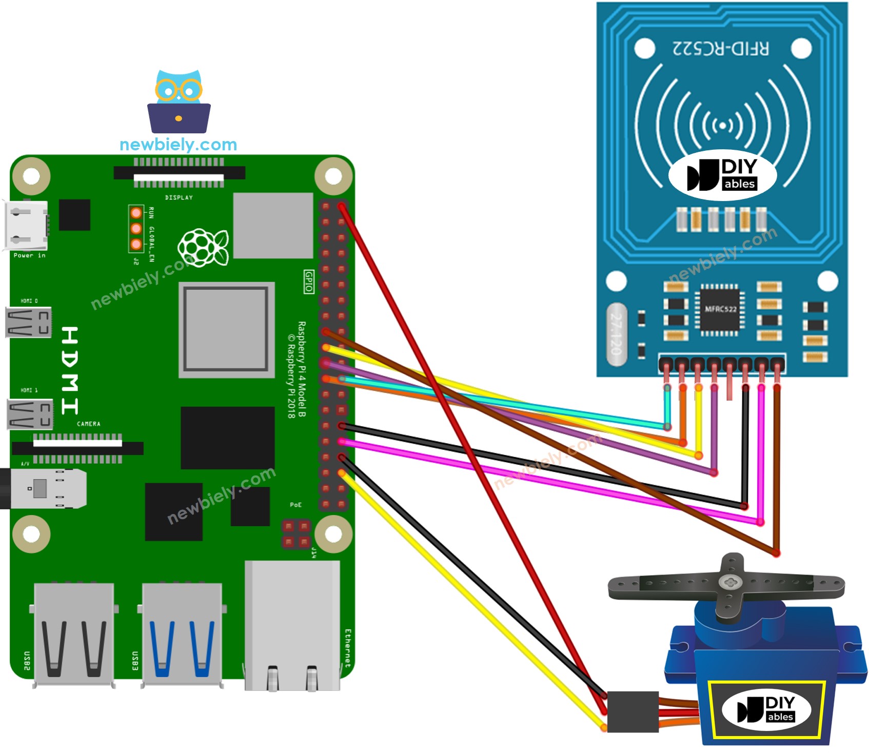
This image is created using Fritzing. Click to enlarge image
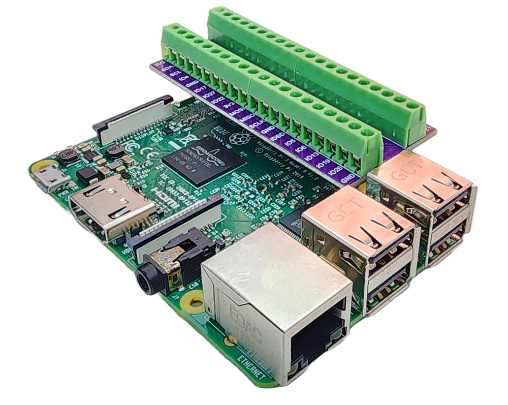
To simplify and organize your wiring setup, we recommend using a Screw Terminal Block Shield for Raspberry Pi. This shield ensures more secure and manageable connections, as shown below:
In the wiring diagram above, a 5V adapter is used to supply power to the Raspberry Pi, the servo motor, and the RC522 module indirectly through the 3.3V pin of the Raspberry Pi.
※ NOTE THAT:
The arrangement of pins may differ depending on the manufacturer. ALWAYS use the labels printed on the module. The image above displays the pinout of modules from DIYables manufacturer.
For the sake of simplicity, the above wiring diagram is used for testing or educational purposes, and for a servo motor with a small torque. We strongly suggest using an external power source for the servo motor in practice. See how to provide the external power for servo motor on the Raspberry Pi - Servo Motor tutorial
Wiring table of RFID/NFC RC522 Module
| RFID/NFC RC522 | Raspberry Pi |
|---|---|
| SS | → GPIO 8 (SPI0 CS) |
| SCK | → GPIO 11 (SPI0 SCL) |
| MOSI | → GPIO 10 (SPI0 MOSI) |
| MISO | → GPIO 9 (SPI0 MISO) |
| IRQ | not connected |
| GND | → Any GND Pin |
| RST | → Pin 31 (GPIO12) |
| VCC | → Pin 1 or Pin 16 (3.3V) |
Wiring table of Servo Motor
| Servo Motor | Arduino | 5V DC Adapter |
|---|---|---|
| VCC (red) | → positive | |
| GND (brown) | → negative | |
| SIG (yellow) | → A5 |
Wiring table of 5V DC Adapter
| 5V DC Adapter | Servo Motor | Raspberry Pi |
|---|---|---|
| Positive | → VCC | |
| Positive | -> Vin | |
| Negative | → GND | |
| Negative | → GND |
Raspberry Pi Code - Single RFID/NFC Tag
Detailed Instructions
- Make sure you have Raspbian or any other Raspberry Pi compatible operating system installed on your Pi.
- Make sure your Raspberry Pi is connected to the same local network as your PC.
- Make sure your Raspberry Pi is connected to the internet if you need to install some libraries.
- If this is the first time you use Raspberry Pi, See how to set up the Raspberry Pi
- Connect your PC to the Raspberry Pi via SSH using the built-in SSH client on Linux and macOS or PuTTY on Windows. See to how connect your PC to Raspberry Pi via SSH.
- Make sure you have the RPi.GPIO library installed. If not, install it using the following command:
- Enable the SPI interface on Raspberry Pi by following the instruction on Raspberry Pi - how to enable SPI inteface
- Make sure you have the spidev library installed. If not, install it using the following command:
- Make sure you have the mfrc522 library installed. If not, install it using the following command:
- Create a Python script file rfid_servo.py and add the following code:
- Save the file and run the Python script by executing the following command in the terminal:
The script runs in an infinite loop continuously until you press Ctrl + C in the terminal.
In order to identify the UID of an RFID/NFC tag, tap an RFID/NFC tag on the RFID-RC522 module. The UID can be seen on the Terminal.
Once you have your UID:
- Replace line 20 of the code with the UID, for example byte authorizedUID[4] = {0x3A, 0xC9, 0x6A, 0xCB};
- Run the Python script again
- Place an RFID/NFC tag on the RFID-RC522 module
- The servo motor will rotate to 90°
- Check out the output on the Terminal
- Tap the same RFID/NFC tag that was used on the RFID-RC522 module once more.
- Check out the servo motor rotate to 0°.
- Check out the output on the Terminal
- Tap an RFID or NFC tag on the RFID-RC522 module.
- Check out the output on the Terminal