Raspberry Pi - Joystick
This tutorial instructs you how to use joystick with Raspberry Pi. We will delve into:
- The fundamentals of how a joystick works
- Connecting joystick to Raspberry Pi and programming for it
- Converting the values from joystick to controllable values such as XY coordinates, the motor's up/down/left/right direction...
Hardware Preparation
Or you can buy the following kits:
| 1 | × | DIYables Sensor Kit (18 sensors/displays) |
Additionally, some of these links are for products from our own brand, DIYables .
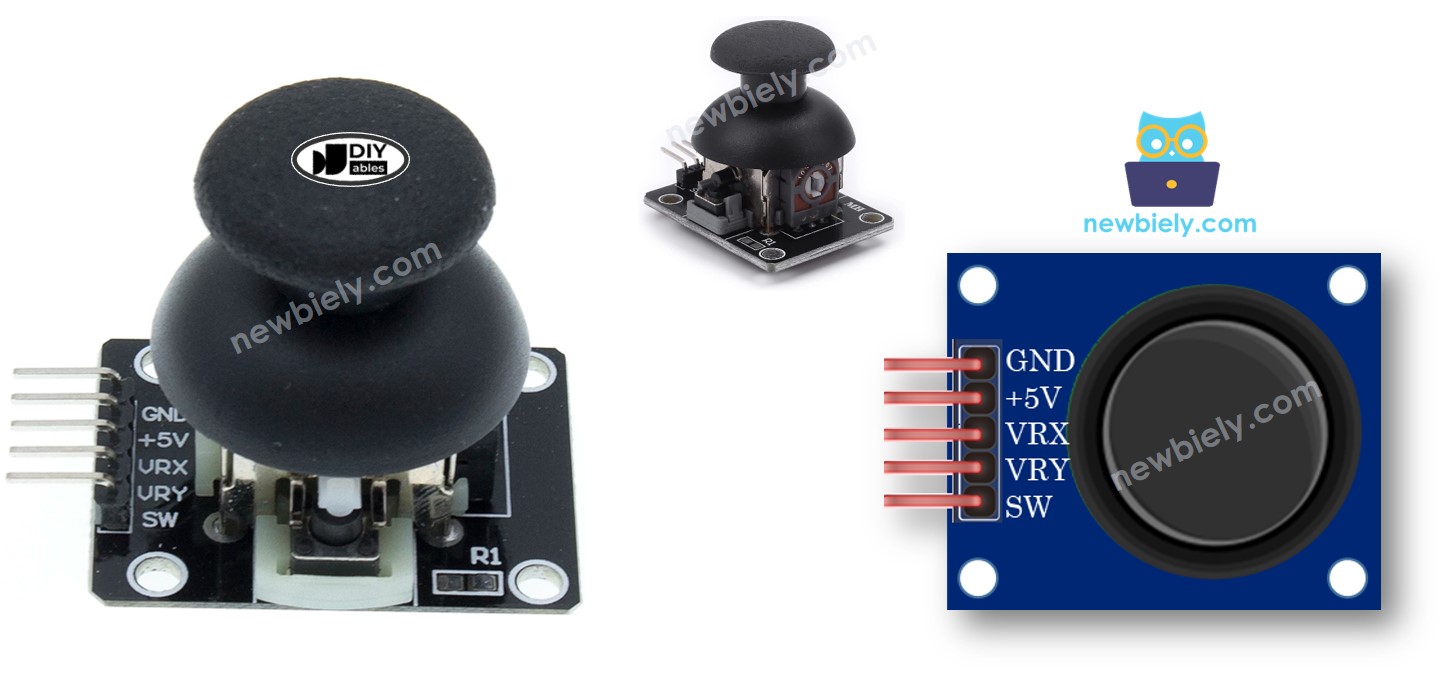
Overview of 2-axis Joystick
You may have encountered a Joystick in various places, such as a game controller, a toy controller, or even a large machine like an excavator controller.
The joystick is made up of two potentiometers arranged in a square shape, and one push button. It provides the following outputs:
- An analog value ranging from 0 to 1023 that corresponds to the horizontal position (known as the X-coordinate)
- An analog value ranging from 0 to 1023 that corresponds to the vertical position (known as the Y-coordinate)
- A digital value of the pushbutton (either HIGH or LOW)
The combination of two analog values can generate 2-D coordinates with the center being the values when the joystick is in its resting position. To determine the actual direction of the coordinates, a test code can be run (presented in the next section).
Some applications may use all three outputs, while others may utilize only some of them.
The Joystick Pinout
A Joystick has 5 pins:
- GND pin: This must be connected to GND (0V).
- VCC pin: This must be connected to VCC (5V).
- VRX pin: This outputs an analog value that corresponds to the horizontal position (known as the X-coordinate).
- VRY pin: This outputs an analog value that corresponds to the vertical position (known as the Y-coordinate).
- SW pin: This is the output from the pushbutton inside the joystick. It is normally open. If a pull-up resistor is used in this pin, the SW pin will be HIGH when it is not pressed, and LOW when it is pressed.
How It Works
- When you move the joystick's thump to the left or right, the voltage in the VRX pin is changed. This voltage range is from 0V to 5V, with 0V being at the left and 5V being at the right, resulting in a reading value on the Raspberry Pi's analog pin from 0 to 1023.
- Similarly, when you move the joystick's thump up or down, the voltage in the VRY pin is changed. This voltage range is from 0V to 5V, with 0V being at the top and 5V being at the bottom, resulting in a reading value on the Raspberry Pi's analog pin from 0 to 1023.
- When you move the joystick's thump in any direction, the voltage in both the VRX and VRY pins is changed in proportion to the projection of the position on each axis.
- When you push the joystick's thump from the top to the bottom, the pushbutton inside the joystick is closed. If we use a pull-up resistor in the SW pin, the output from the SW pin will change from 5V to 0V, resulting in a reading value on the Raspberry Pi's digital pin changing from HIGH to LOW.
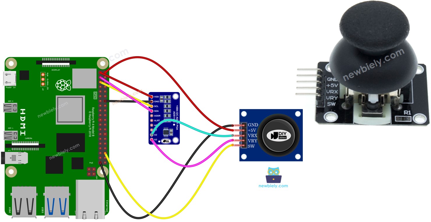
Wiring Diagram
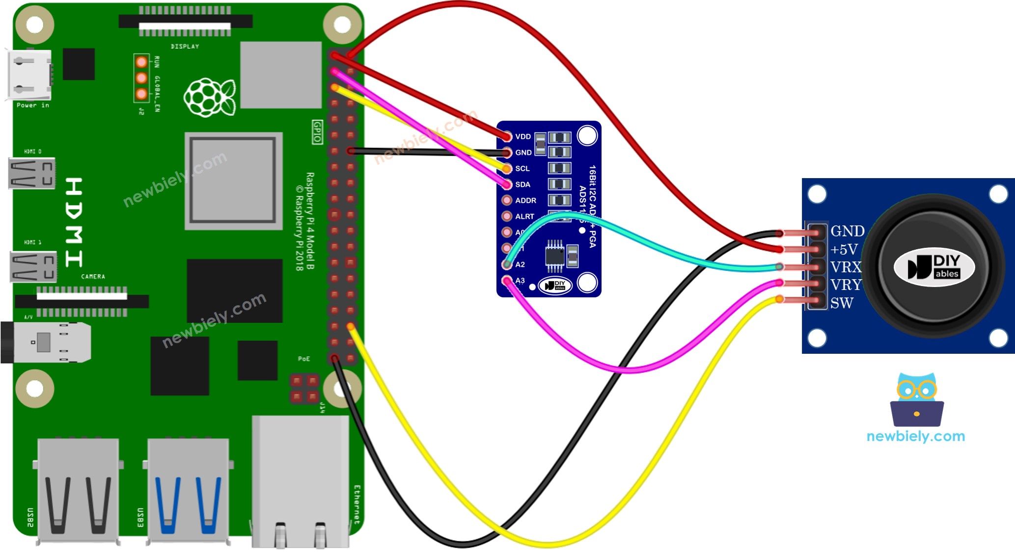
This image is created using Fritzing. Click to enlarge image
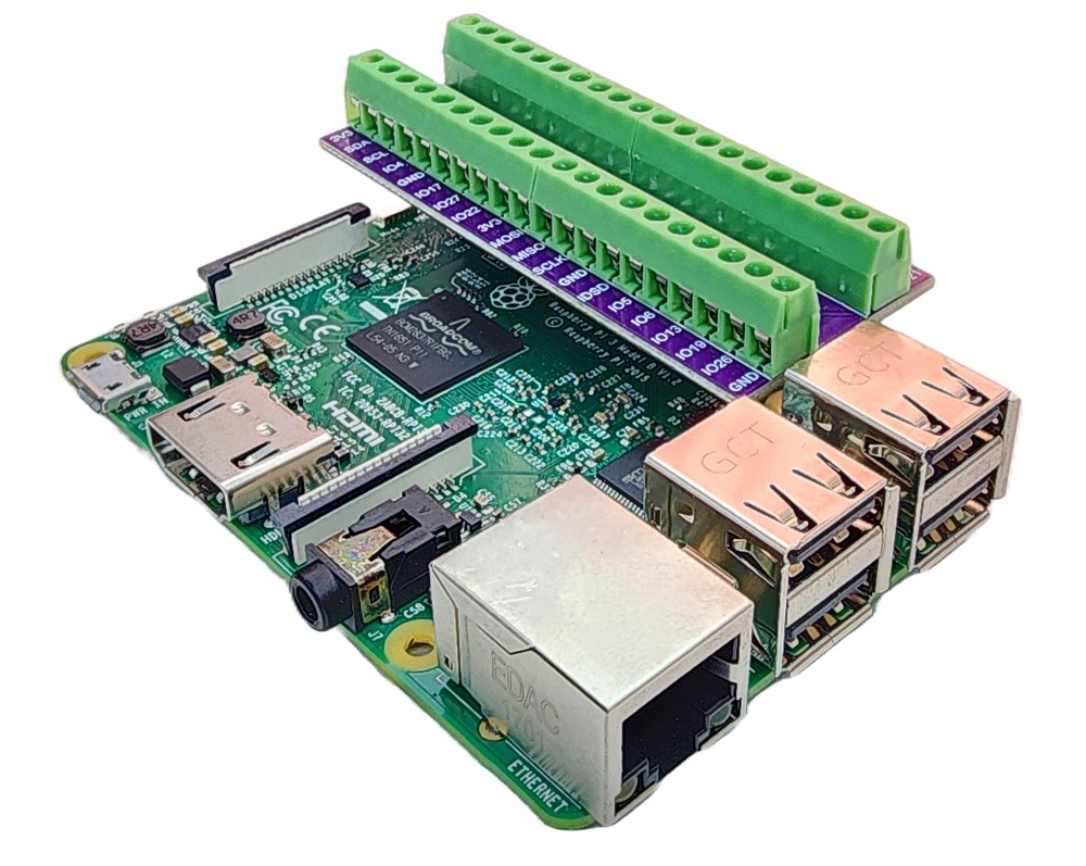
To simplify and organize your wiring setup, we recommend using a Screw Terminal Block Shield for Raspberry Pi. This shield ensures more secure and manageable connections, as shown below:
Raspberry Pi Code
This section will present the following Raspberry Pi example codes:
- Example code: Obtaining analog values from joystick
- Example code: Obtaining analog values and button state from joystick
- Example code: Converting analog value to MOVE_LEFT, MOVE_RIGHT, MOVE_UP, MOVE_DOWN commands
- Example code: converting analog values to angles for controlling two servo motors (e.g. in pan-tilt camera)
Reads analog values from joystick
Detailed Instructions
- Make sure you have Raspbian or any other Raspberry Pi compatible operating system installed on your Pi.
- Make sure your Raspberry Pi is connected to the same local network as your PC.
- Make sure your Raspberry Pi is connected to the internet if you need to install some libraries.
- If this is the first time you use Raspberry Pi, See how to set up the Raspberry Pi
- Connect your PC to the Raspberry Pi via SSH using the built-in SSH client on Linux and macOS or PuTTY on Windows. See to how connect your PC to Raspberry Pi via SSH.
- Make sure you have the RPi.GPIO library installed. If not, install it using the following command:
- Install the Adafruit_ADS1x15 library by running the following commands on your Raspberry Pi terminal:
- Create a Python script file joystick.py and add the following code:
- Save the file and run the Python script by executing the following command in the terminal:
- Push the joystick's thump to its maximum and then rotate it in either a clockwise or counterclockwise direction.
- Check the results on the Terminal.
While turning the joystick's thumb, keep an eye on the Terminal.
If the X value is 0, note or remember the current position as left, with the opposite direction being right.
If the Y value is 0, note or remember the current position as up, with the opposite direction being down.
The script runs in an infinite loop continuously until you press Ctrl + C in the terminal.
Reads analog values and reads the button state from a joystick
Detailed Instructions
- Create a Python script file joystick_sw.py and add the following code:
- Save the file and run the Python script by executing the following command in the terminal:
- Move the joystick's thumb to the left, right, up, or down.
- Push the joystick's thumb from the top.
- Check the results on the Terminal.
Converts analog value to MOVE LEFT/RIGHT/UP/DOWN commands
Detailed Instructions
- Create a Python script file joystick_cmd.py and add the following code:
- Save the file and run the Python script by executing the following command in the terminal:
- Move the joystick in any direction.
- Check the result in the Terminal.
※ NOTE THAT:
At a given moment, there may be no command, one command, or two commands simultaneously (e.g. UP and LEFT).
Converts analog values to angles to control two servo motors
The specifics can be found in the tutorial titled Raspberry Pi - Joystick controls Servo Motor.