Raspberry Pi - Rotary Encoder
This tutorial instructs you how to use the incremental rotary encoder with Raspberry Pi. Here's what we'll cover:
- How the rotary encoder works
- The difference between a rotary encoder and a potentiometer (another type of knob)
- How to physically connect the rotary encoder to an Raspberry Pi
- How to write code for the Raspberry Pi to read the direction and position from the rotary encoder.
Hardware Preparation
Or you can buy the following kits:
| 1 | × | DIYables Sensor Kit (18 sensors/displays) |
Additionally, some of these links are for products from our own brand, DIYables .
Overview of Rotary Encoder
A spinning knob that turns movement into a signal is called a rotary encoder. It shows you how much something twisted and where it's placed. There are two main kinds:
- Incremental encoder: This uses fast signals to measure how much something changed.
- Absolute encoder: This kind provides a unique code for each position, so you know exactly where something is, even if the power goes off.
This guide concentrates on the incremental encoder.
Rotary Encoder Module Pinout
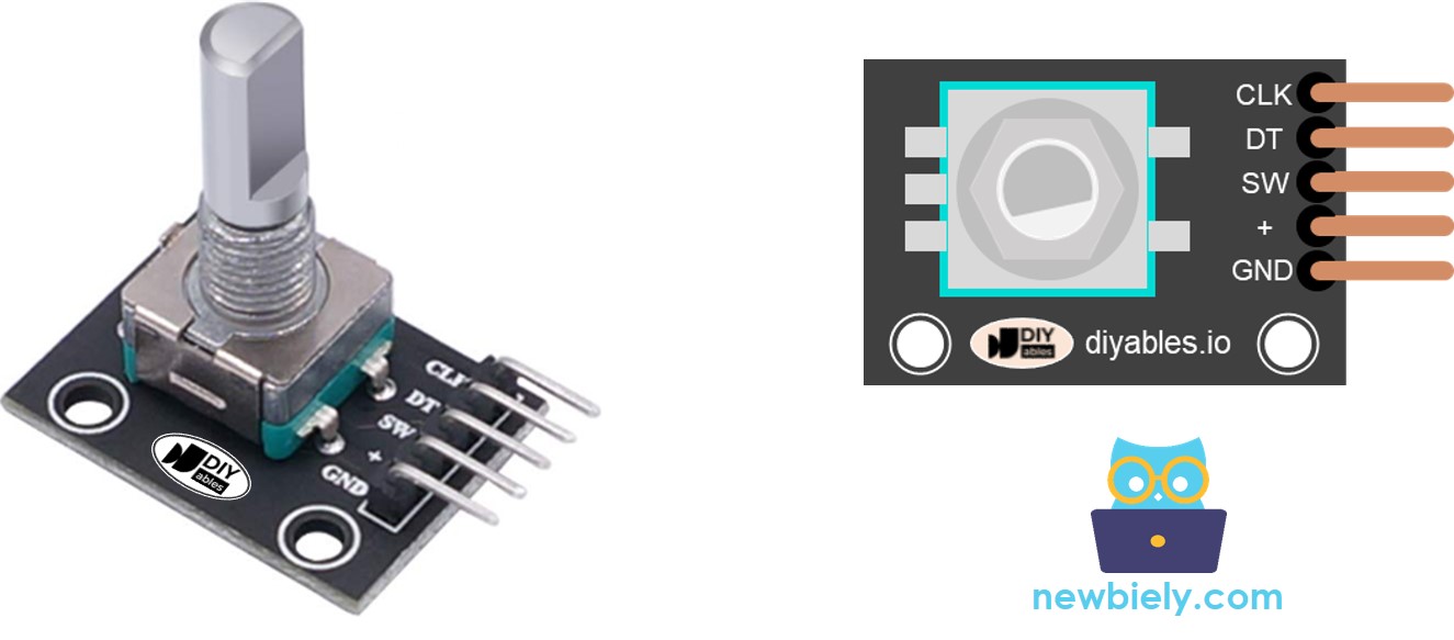
A rotary encoder module has 4 pins:
- CLK pin (Output A): is the main pulse that tells us how much rotation has occurred. Whenever you turn the knob by one detent (click) in either direction, the CLK pin outputs a signal that is a completes a full cycle (LOW → HIGH → LOW).
- DT pin (Output B): acts like the CLK pin but outputs a signal lags behind CLK signal by 90 degrees. It helps us figure out the direction of rotation (clockwise or anticlockwise).
- SW pin: is the output from the pushbutton inside the encoder. It’s normally open. If we use a pull-up resistor in this pin, the SW pin will be HIGH when the knob is not pressed, and LOW when it is pressed.
- VCC pin (+): needs to be connected to VCC (between 3.3 and 5 volts)
- GND pin: needs to be connected to GND (0V)
Rotary Encoder vs Potentiometer
You may confuse the rotary encoder with the potentiometer. but they are distinct components. Here's a comparison between them:
- Rotary encoder is like the modern version of potentiometer, but they can do more things.
- Rotary encoder can spin around in a full circle without stopping, while potentiometer can only turn about three-quarters of the circle.
- Rotary encoder outputs pulses, while potentiometer outputs the analog voltage.
- Rotary encoder is handy when you just need to figure out how much the knob has moved, not exactly where it is. Potentiometer is useful when you really need to know exactly where a knob is.
How Rotary Encoder Works
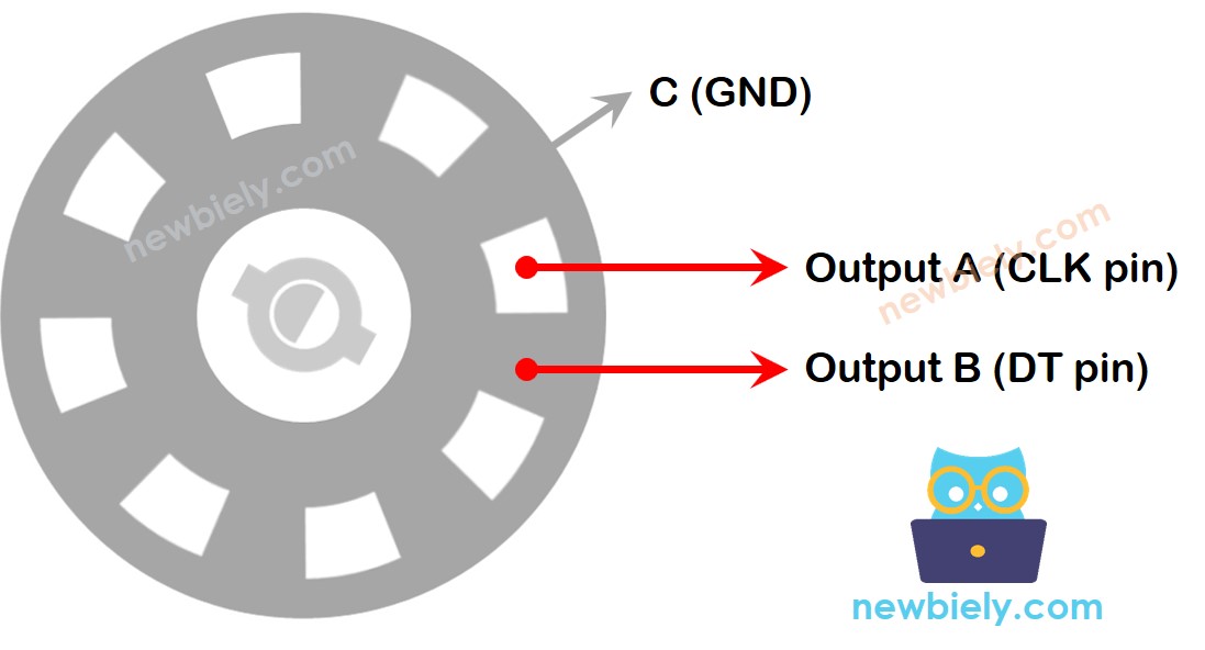
Inside the encoder, there's a disc with slots connected to a pin called C, which is like a shared ground. There are two more pins, A and B.
- When you twist the knob, pins A and B touch the shared ground pin C, but in a certain order depending on which way you turn the knob (clockwise or counter-clockwise).
- These touches create two signals. They're a bit different in timing because one pin touches the ground before the other. Two signals are 90 degrees out of sync with each other. This is called quadrature encoding.
- When you turn the knob in clockwise direction, pin A touches the ground before pin B. When you turn the knob to the counterclockwise direction, pin B touches the ground before pin A.
- By monitoring when each pin touches or leaves the ground, we can figure out which way the knob is turning. We do this by checking what happens to pin B when pin A changes.
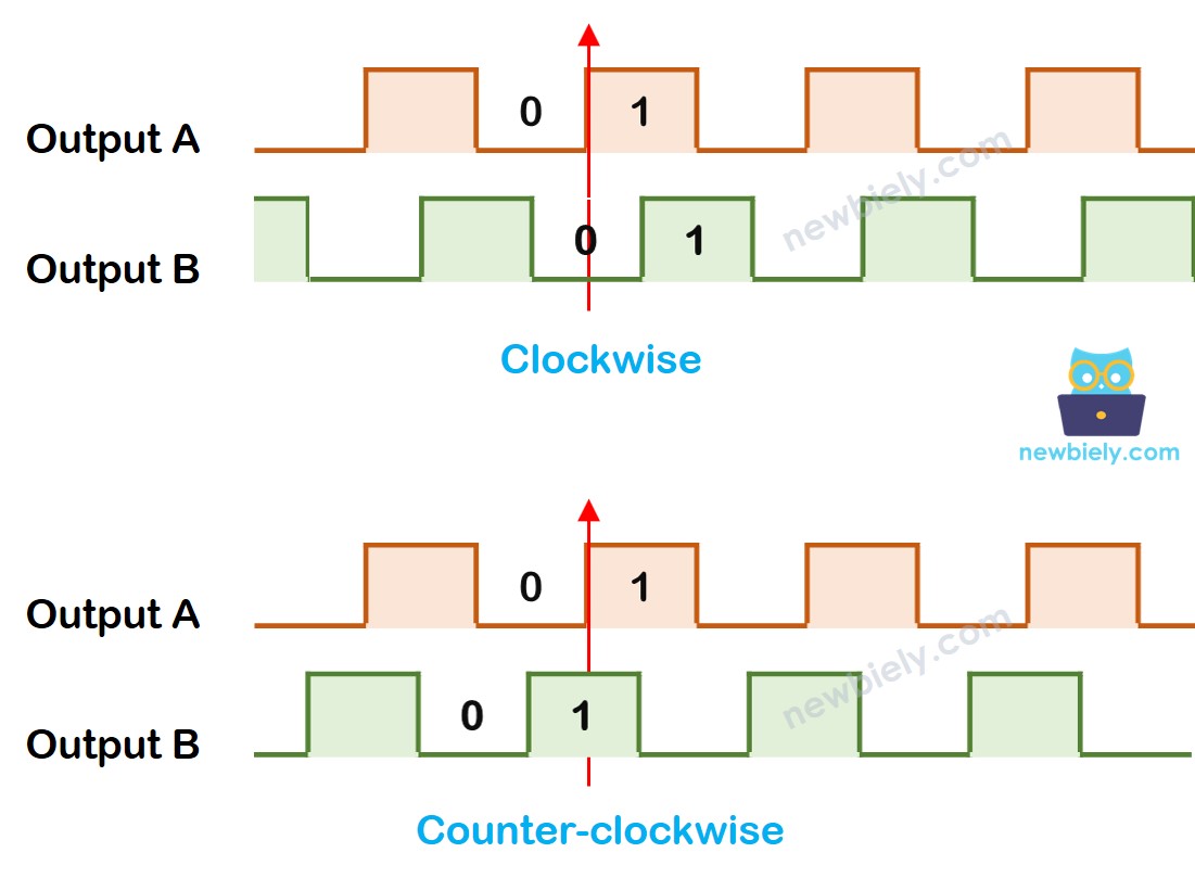
When A changes states from LOW to HIGH:
- If B is LOW, the knob is turned clockwise.
- If B is HIGH, the knob is turned counter-clockwise.
※ NOTE THAT:
Pin A and B are connected to CLK and DT pins. However, depending on the manufacturers, the order may be different. The codes provided below are tested with the rotary encoder from DIYables
How To Program For Rotary Encoder
- Check the signal from CLK pin
- If the state changes from LOW to HIGH, check the state of the DT pin.
- If the state of the DT pin is HIGH, the knob is turned in the counter-clockwise direction, increase the counter by 1
- If the state of the DT pin is LOW, the knob is turned in the clockwise direction, decrease the counter by 1
Wiring Diagram
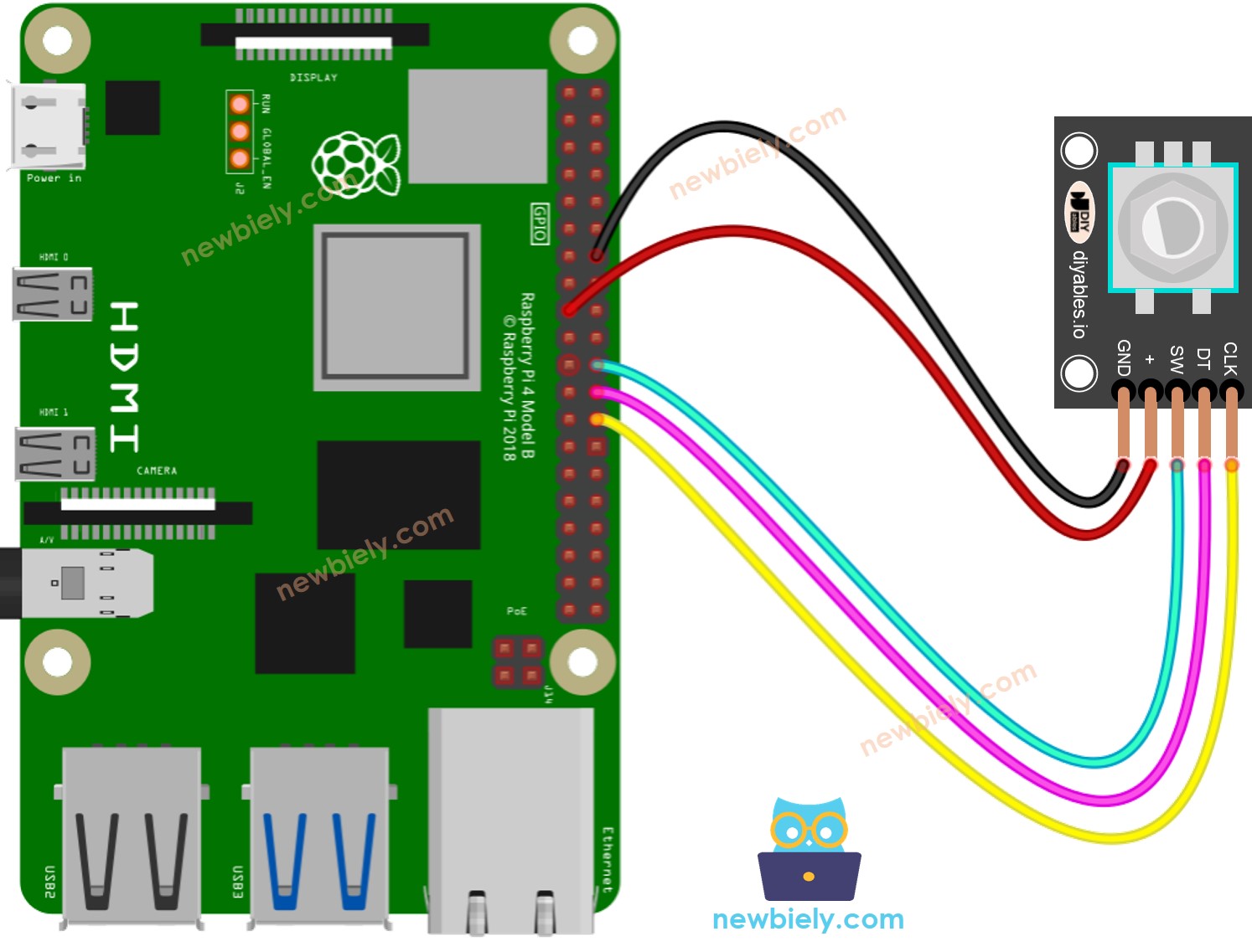
This image is created using Fritzing. Click to enlarge image
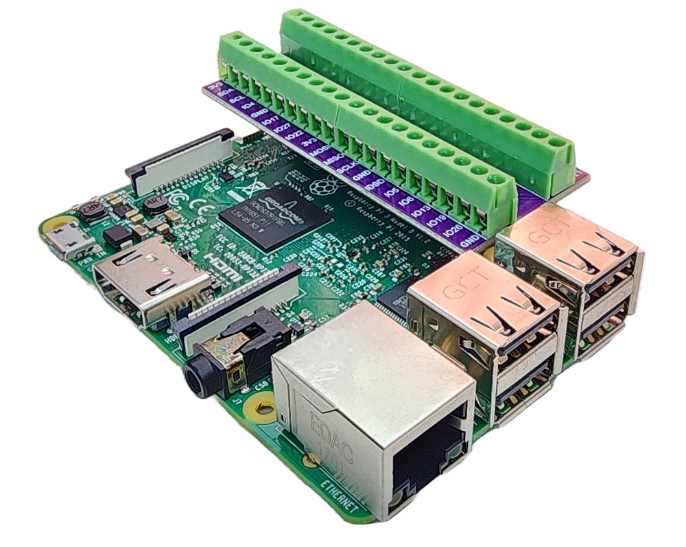
To simplify and organize your wiring setup, we recommend using a Screw Terminal Block Shield for Raspberry Pi. This shield ensures more secure and manageable connections, as shown below:
Raspberry Pi Code – Rotary Encoder
The below Raspberry Pi code does:
- Detects the direction and amount of rotation of the encoder.
- If detecting the knob turned by one detent (click) in clockwise direction, increase the counter by one.
- If detecting the knob turned by one detent (click) in anticlockwise direction, decrease the counter by one.
- Detects if the button is pressed.
Detailed Instructions
- Make sure you have Raspbian or any other Raspberry Pi compatible operating system installed on your Pi.
- Make sure your Raspberry Pi is connected to the same local network as your PC.
- Make sure your Raspberry Pi is connected to the internet if you need to install some libraries.
- If this is the first time you use Raspberry Pi, See how to set up the Raspberry Pi
- Connect your PC to the Raspberry Pi via SSH using the built-in SSH client on Linux and macOS or PuTTY on Windows. See to how connect your PC to Raspberry Pi via SSH.
- Make sure you have the RPi.GPIO library installed. If not, install it using the following command:
- Create a Python script file rotary_encoder.py and add the following code:
- Save the file and run the Python script by executing the following command in the Terminal:
- Turn the knob in clockwise, then counterclockwise
- Press the knob
- Check out the outcome in the Terminal.
Code Explanation
Check out the line-by-line comments in the code
Raspberry Pi Rotary Encoder Application
With Rotary Encoder, we can do the following applications but not limit:
- Raspberry Pi - Rotary Encoder controls Position of Sevo Motor
- Raspberry Pi - Rotary Encoder controls Brightness of LED
- Raspberry Pi - Rotary Encoder controls Speed of Stepper Motor