Arduino UNO R4 - Actuator
Discover how to use the Arduino Uno R4 to control a linear actuator in this easy tutorial! Perfect for beginners, this guide shows you how to use an L298N driver for fun DIY projects. Here’s what you’ll learn:
- What a linear actuator is and how it moves
- Simple steps to make the actuator extend or retract
- Easy wiring with the L298N driver
- Clear Arduino code to control the actuator
- How to change the actuator’s speed to move faster or slower
This tutorial is about linear actuators without feedback. If you want to learn about linear actuators with feedback, visit our Arduino UNO R4 - Actuator with Feedback guide. Follow this easy Arduino project to build your own smart automation system!
Hardware Preparation
Or you can buy the following kits:
| 1 | × | DIYables STEM V4 IoT Starter Kit (Arduino included) | |
| 1 | × | DIYables Sensor Kit (18 sensors/displays) |
Additionally, some of these links are for products from our own brand, DIYables .

Overview of Linear Actuator

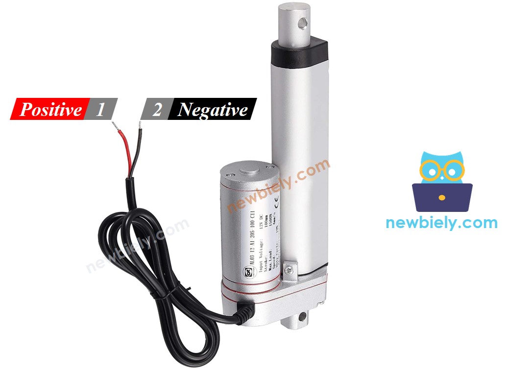
Linear Actuator Pinout
A linear actuator comes with two wires.
- Positive wire: often red
- Negative wire: often black
How It Works
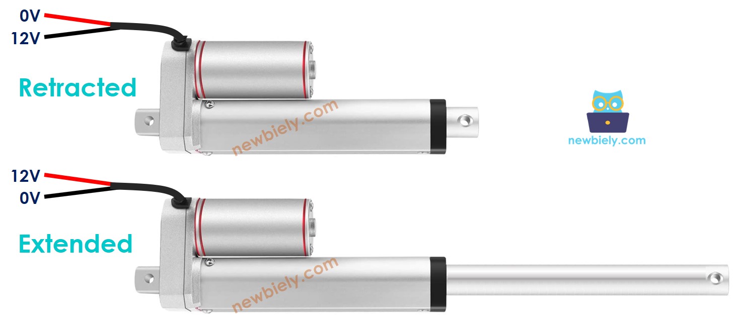
When purchasing a linear actuator, it's important to understand which voltage it operates on. For instance, consider a linear actuator that uses 12 volts.
When you connect the 12V linear actuator to a 12V power supply:
- Connect 12V to the positive wire and GND to the negative wire: the linear actuator extends fully at high speed until it stops at its limit.
- Connect 12V to the negative wire and GND to the positive wire: the linear actuator retracts fully at high speed until it stops at its limit.
When you cut off the power to the actuator by connecting both the positive and negative wires to the ground, the actuator will stop moving in or out.
※ NOTE THAT:
For DC motors, servo motors, and stepper motors without gears, they cannot maintain their position when the power is turned off and they are carrying a load. However, an actuator can maintain its position even without power when it is carrying a load.
If we use less than 12V for linear actuators, they still work but not at their fastest speed. This shows that changing the power supply voltage can adjust the speed of the linear actuator. However, controlling the voltage precisely is difficult, so this method is not commonly used. Instead, the voltage is kept constant and the speed of the linear actuator is controlled using a PWM signal. When the PWM duty cycle is higher, the linear actuator moves faster.
How to Control a Linear Actuator with Arduino Uno R4
To control a linear actuator, we usually want to:
- Make it extend (move out) at full speed
- Make it retract (move back in) at full speed
- (Optional) Control how fast it moves in or out
The Arduino can send control signals, but these signals are too weak (low voltage and current) to move the actuator directly. That’s why we need a driver between the Arduino and the actuator.
The driver does two main jobs:
- It boosts (amplifies) the Arduino’s signal so it can power the actuator.
- It switches the power direction (by changing the polarity) based on another signal from the Arduino — this controls whether the actuator extends or retracts.
※ NOTE THAT:
- You can use this guide for any linear actuator. We use a 12V linear actuator as an example.
- When using a 5V linear actuator with an Arduino UNO R4, even though both use 5V, you need to add a driver. This is because the Arduino UNO R4 cannot supply enough current for the actuator.
This guide uses the L298N driver, but there are various other chips and modules, like L293D, that can also control linear actuators.
Overview of L298N Driver
The L298N Driver can control devices like linear actuators, DC motors, and stepper motors. In this tutorial, we will show how to use it to control a linear actuator.
L298N Driver Pinout
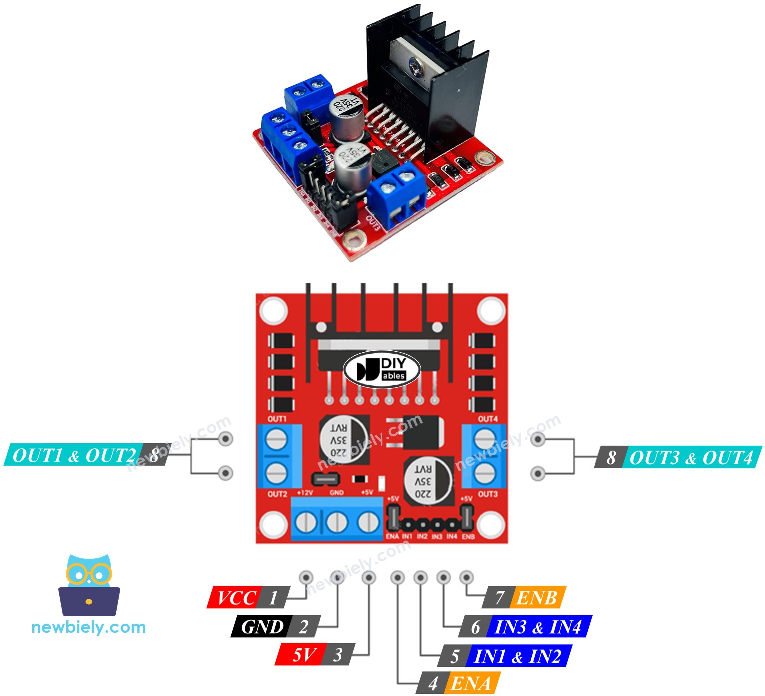
The L298N Driver features two separate channels, known as channel A and channel B. This setup allows the L298N Driver to manage two different linear actuators independently and simultaneously. Suppose linear actuator A is linked to channel A and linear actuator B to channel B. The L298N Driver comprises 13 pins.
The common pins for both channels:
- VCC pin: provides power to the linear actuator. It accepts a range from 5 to 35V.
- GND pin: serves as a common ground and should be connected to GND (0V).
- 5V pin: powers the L298N module. You can use 5V from an Arduino UNO R4 for this.
Channel A pins:
- ENA pins: help manage how fast linear actuator A moves. If you disconnect the jumper and link this pin to a PWM input, you can adjust the speed at which it extends or retracts.
- IN1 & IN2 pins: determine the direction the linear actuator moves. If one pin is HIGH and the other is LOW, the actuator will either extend or retract. If both are HIGH or both are LOW, the actuator will stop moving.
- OUT1 & OUT2 pins: are linked to linear actuator A.
Channel B pins:
- ENB pins: These pins adjust the speed of linear actuator B. Disconnect the jumper and use a PWM input with this pin to control how fast linear actuator B extends or retracts.
- IN3 & IN4 pins: These pins determine the direction of a linear actuator's movement. If one pin is HIGH and the other is LOW, the linear actuator will either extend or retract. If both pins are HIGH or LOW, the linear actegrator will stop.
- OUT3 & OUT4 pins: These are connected to a linear actuator.
The L298N driver has two types of input power:
- One for the linear actuator (VCC and GND pins): from 5 to 35V.
- One for the internal operation of the L298N module (5V and GND pins): from 5 to 7V.
The L298N driver comes with three jumpers for special or different uses. For simplicity, please take off all the jumpers from the L298N driver.
We can manage two linear actuators independently and simultaneously using an Arduino UNO R4 and an L298N Driver. To operate each linear actuator, we require just three pins from the Arduino UNO R4.
※ NOTE THAT:
This part of the guide shows how to use channel A to control a linear actuator. Controlling another linear actuator works in a similar way.
How To Control Linear Actuator
We will learn how to use the L298N driver to control a Linear Actuator.
Wiring Diagram
Before you start wiring, take off all three jumpers from the L298N module.
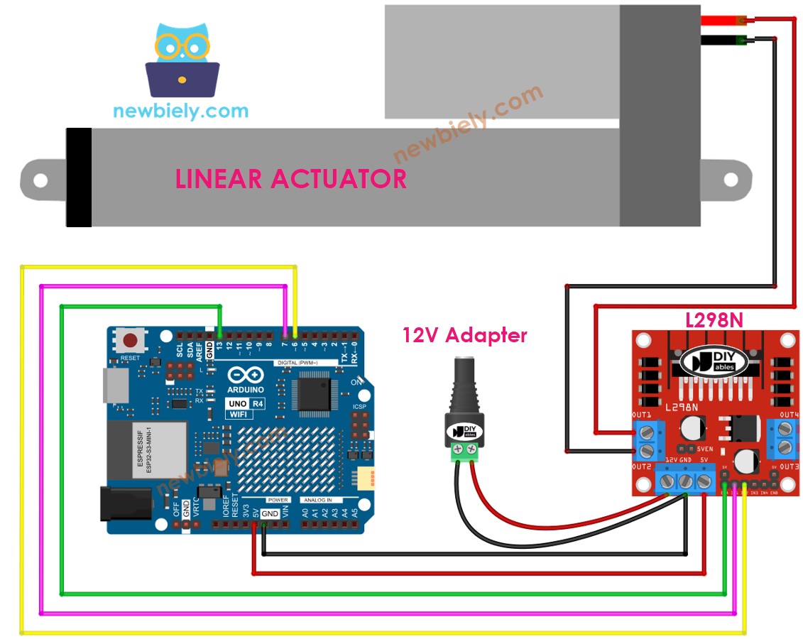
This image is created using Fritzing. Click to enlarge image
See The best way to supply power to the Arduino Uno R4 and other components.
How To Make Linear Actuator Expand/Retract
You can control the direction of a Linear Actuator by setting the IN1 and IN2 pins to either HIGH or LOW. The table below shows how to do this for both channels.
| IN1 pin | IN2 pin | Direction |
|---|---|---|
| LOW | LOW | Linear Actuator A stops |
| HIGH | HIGH | Linear Actuator A stops |
| HIGH | LOW | Linear Actuator A extends |
| LOW | HIGH | Linear Actuator A retracts |
- Lengthens Linear Actuator A
- Linear actuator A retracts.
※ NOTE THAT:
If the OUT1 and OUT2 pins are connected to the linear actuator incorrectly, the direction will be reversed. To fix this, simply switch the positions of the OUT1 and OUT2 pins or change the control signals on the IN1 and IN2 pins in the program.
How To Stop Linear Actuator from Extending or Retracting
The linear actuator stops moving out or back automatically when it gets to its maximum or minimum point. We can also set it to stop moving before it reaches these points.
There are two methods to halt a linear actuator.
- Sets the speed to zero
- Sets IN1 and IN2 pins to the same level (LOW or HIGH).
- Please check the grammar and punctuation before publishing this document.
How To Control the Speed of Linear Actuator via L298N Driver
To easily adjust the speed of the linear actuator, use a PWM signal on the ENA pin instead of setting it to HIGH. Here’s how you can do it:
- Connect an Arduino UNO R4 pin to the ENA pin on the L298N module.
- Use the analogWrite() function to send a PWM signal to the ENA pin. The L298N driver will increase this signal to control the linear actuator.
The speed can be any number from 0 to 255. At speed 0, the linear actuator will stop. At speed 255, it moves at its fastest speed.
Arduino UNO R4 Example Code
This code performs the following tasks:
- Move the actuator out as fast as possible
- Stop the actuator
- Move the actuator back in as fast as possible
- Stop the actuator
Detailed Instructions
Follow these instructions step by step:
- If this is your first time using the Arduino Uno R4 WiFi/Minima, refer to the tutorial on setting up the environment for Arduino Uno R4 WiFi/Minima in the Arduino IDE.
- Wire the components according to the provided diagram.
- Connect the Arduino Uno R4 board to your computer using a USB cable.
- Launch the Arduino IDE on your computer.
- Select the appropriate Arduino Uno R4 board (e.g., Arduino Uno R4 WiFi) and COM port.
- Take off all three jumpers from the L298N module.
- Paste the code into Arduino IDE.
- Press the Upload button in Arduino IDE to transfer the code to Arduino UNO R4.
- Observe the following:
- The linear actuator extends and stops upon reaching its limit.
- The linear actuator holds its position for a period of time.
- The linear actuator retracts and stops upon reaching its limit.
- The linear actuator holds its position for a period of time.
- This sequence repeats continuously.
Video Tutorial
Summary
In this Arduino UNO R4 tutorial, you learned how to control a linear actuator with an L298N driver for DIY automation. This easy guide showed you how to make the actuator move in and out, wire the L298N driver, and change its speed using Arduino programming. Focused on linear actuators without feedback, this simple Arduino project helps you build smart automation systems. Now you can use these skills to create your own motion control projects with Arduino UNO R4!