Arduino UNO R4 - Measure Voltage
In this guide, we will learn how to measure voltage ranging from 0V to 25V using a voltage sensor with an Arduino UNO R4. We will discuss:
- How to link the voltage sensor with Arduino UNO R4
- How to code Arduino UNO R4 to measure voltage from the sensor
Hardware Preparation
Or you can buy the following kits:
| 1 | × | DIYables STEM V4 IoT Starter Kit (Arduino included) | |
| 1 | × | DIYables Sensor Kit (18 sensors/displays) |
Additionally, some of these links are for products from our own brand, DIYables .

Overview of Voltage Sensor
A Voltage Sensor is a ready-made circuit called a voltage divider, using accurate resistors to make measuring voltage easy. It has two resistors, 30 KΩ and 7.5 KΩ. With a 5V reference voltage for the ADC, this sensor can measure voltages between 0 and 25V DC. If the ADC's reference voltage is 3.3V, it can measure voltages from 0 to 16.5V DC.
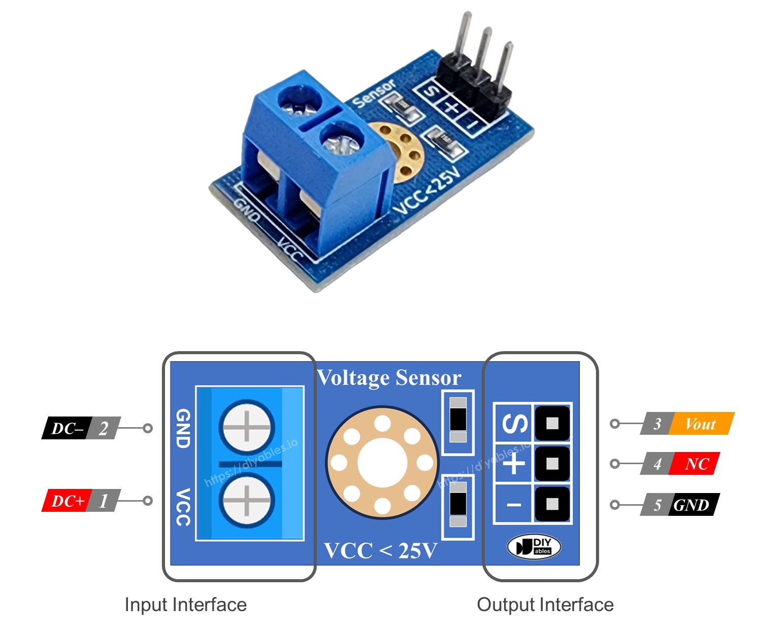
Pinout
A voltage sensor has two types of pins:
- Input Interface (connect it where you need to measure voltage):
- VCC pin: This is the positive pin. Connect it to where the voltage is higher.
- GND pin: This is the negative pin. Connect it to where the voltage is lower.
- Output Interface (connect to the Arduino UNO R4):
- Vout pin (S): This is the signal pin. Connect it to an analog pin on the Arduino UNO R4.
- NC pin (+): Do not connect this; it is not used.
- G& pin (-): This is the ground pin. Connect it to the GND (0V) on the Arduino UNO R4.
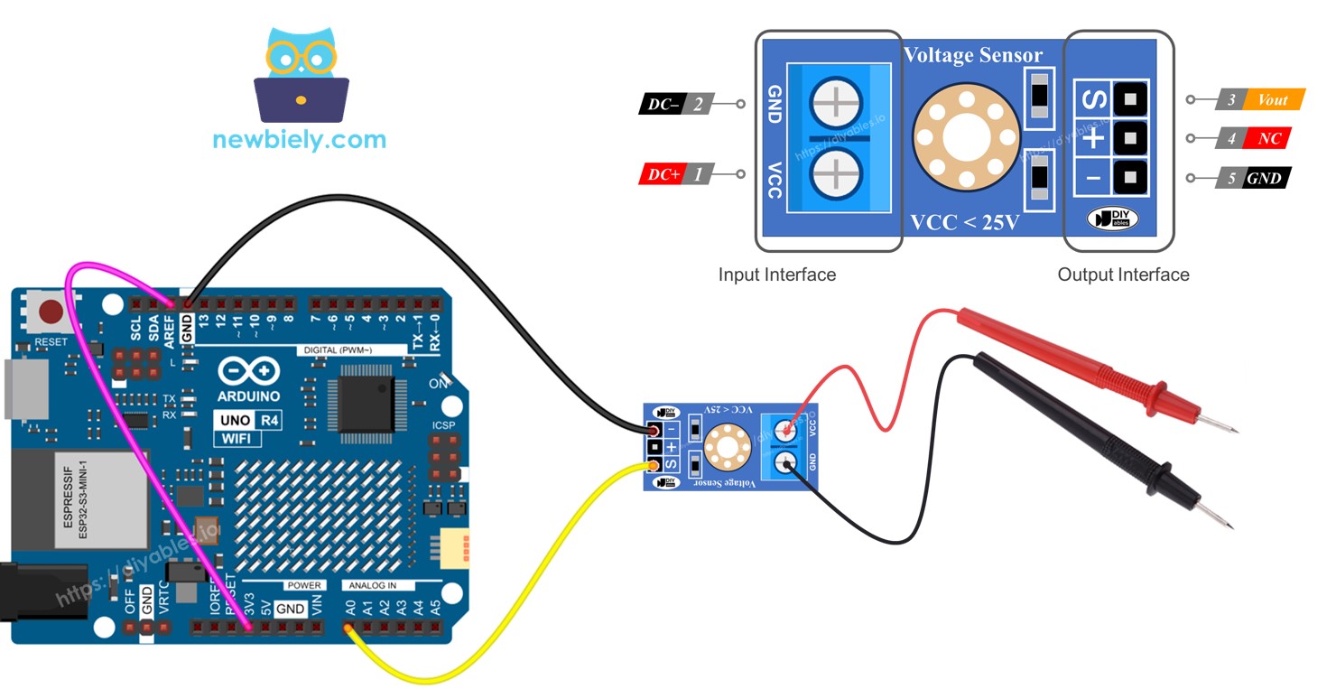
Wiring Diagram
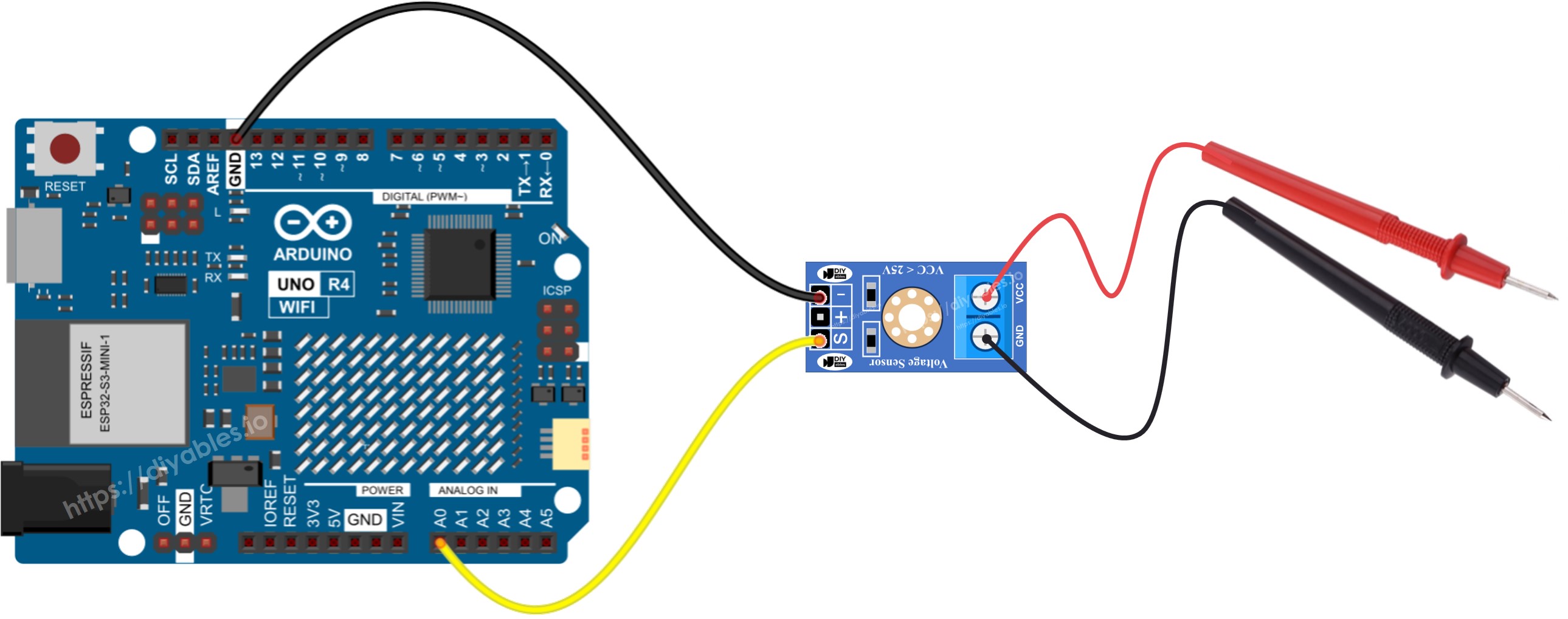
This image is created using Fritzing. Click to enlarge image
Arduino UNO R4 Code
Detailed Instructions
Follow these instructions step by step:
- If this is your first time using the Arduino Uno R4 WiFi/Minima, refer to the tutorial on setting up the environment for Arduino Uno R4 WiFi/Minima in the Arduino IDE.
- Connect the Arduino UNO R4 to the voltage sensor.
- Connect the Arduino Uno R4 board to your computer using a USB cable.
- Launch the Arduino IDE on your computer.
- Select the appropriate Arduino Uno R4 board (e.g., Arduino Uno R4 WiFi) and COM port.
- Copy the code provided and open it in the Arduino IDE.
- Click the Upload button in the Arduino IDE to transfer the code to the Arduino UNO R4.
- Test by measuring 5V and 3.3V on the Arduino UNO R4.
- Check the results on the Serial Monitor.
The measurement result might be wrong or very different from the real value. This is not the fault of the voltage sensor module. The issue could be because the standard voltage reference is 5V, which might be unstable and varies with the power source. Here are some ways to fix this problem:
- Make sure to use a power supply that gives the right amount of voltage for the Arduino UNO R4. Check if the 5V pin on the Arduino UNO R4 is really giving out 5V by using a voltmeter.
- Use an external 3.3V voltage reference. Remember, this way you can only measure voltages between 0 and 16.5V DC.
Measuring Voltage with a 3.3V Reference
To use this method, first prepare the hardware and the code. For the hardware, connect the AREF pin on the Arduino UNO R4 to 3.3V as the diagram shows.
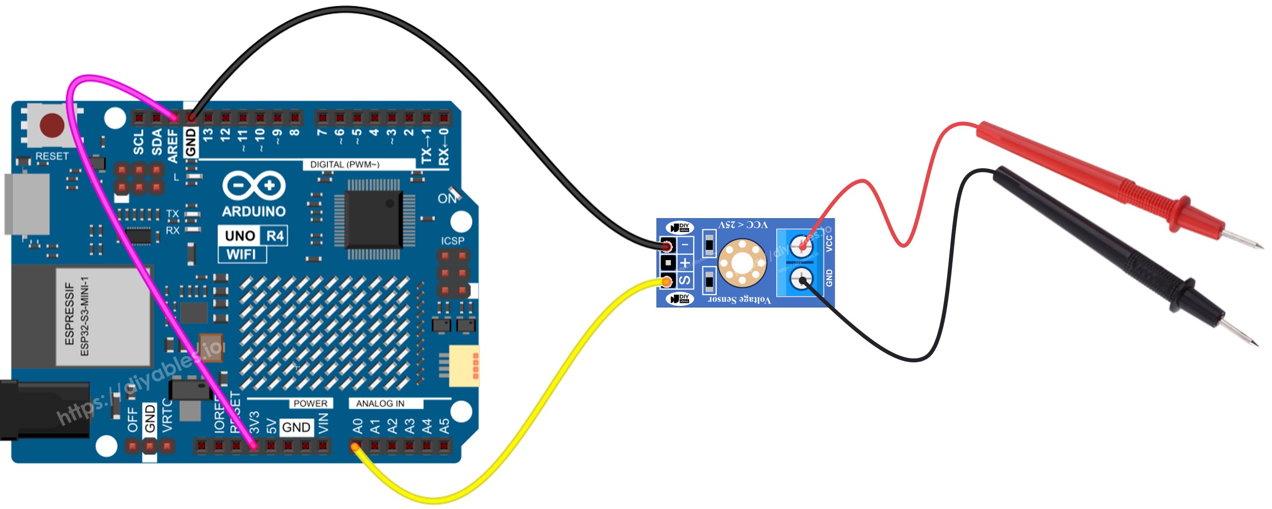
This image is created using Fritzing. Click to enlarge image
See The best way to supply power to the Arduino Uno R4 and other components.
Next, use this code: