Arduino UNO R4 - Actuator with Feedback

This Arduino UNO R4 tutorial shows how to use a *feedback linear actuator* in your DIY projects.

In the previous lesson, we used a linear actuator without feedback. That type only moves in or out, but doesn’t tell us its position.

Now, we’ll learn about a feedback linear actuator. It can tell us where it is while moving, so we can control its exact position.

In this simple guide, you’ll learn:

This simple Arduino project is good for beginners. Follow this easy guide to learn Arduino programming and make a smart moving system!

Overview of Feedback Linear Actuator

A feedback linear actuator is a type of linear actuator that includes a feedback signal to monitor and control its position. This feedback comes from a potentiometer that provides a voltage output corresponding to the actuator's position.

Feedback Linear Actuator Pinout

A Feedback Linear Actuator has five wires:

  • Actuator Positive Wire: This wire controls the linear actuator using high voltage (12V, 24V, 48V).
  • 5V Wire: This wire connects to the feedback potentiometer. Attach it to 5V or 3.3V.
  • GND Wire: This wire connects to the feedback potentiometer. Attach it to the ground (GND).
  • Potentiometer Wire: Also known as the feedback or output wire, this wire sends out a voltage value that changes based on the position of the stroke.
Feedback Linear Actuator Pinout

How It Works

When we supply a high voltage to the positive and negative wires, the actuator will either extend or retract. Specifically, if we connect:

  • Connect 12V (like 12V, 24V, 48V...) and GND to the positive and negative wires respectively: the linear actuator extends at full speed until it stops at the end.
  • Connect 12V (like 12V, 24V, 48V...) and GND to the negative and positive wires respectively: the linear actuator retracts at full speed until it stops at the end.
  • If power is cut off from the actuator (GND connected to both positive and negative wires) while it is extending or retracting, the actuator will stop moving.

※ NOTE THAT:

  • The voltage needed to control the actuator varies based on its specifications. Check the datasheet or manual to find out the right voltage.
  • The actuator can maintain its position without power, even if it is holding a weight.

The voltage in the wire of the potentiometer changes according to where the actuator moves. By checking this voltage, we can find out where the stroke is positioned.

Wiring Diagram

Before wiring, take off all three jumpers from the L298N module.

The wiring diagram between Arduino UNO R4 Linear Actuator L298N Driver

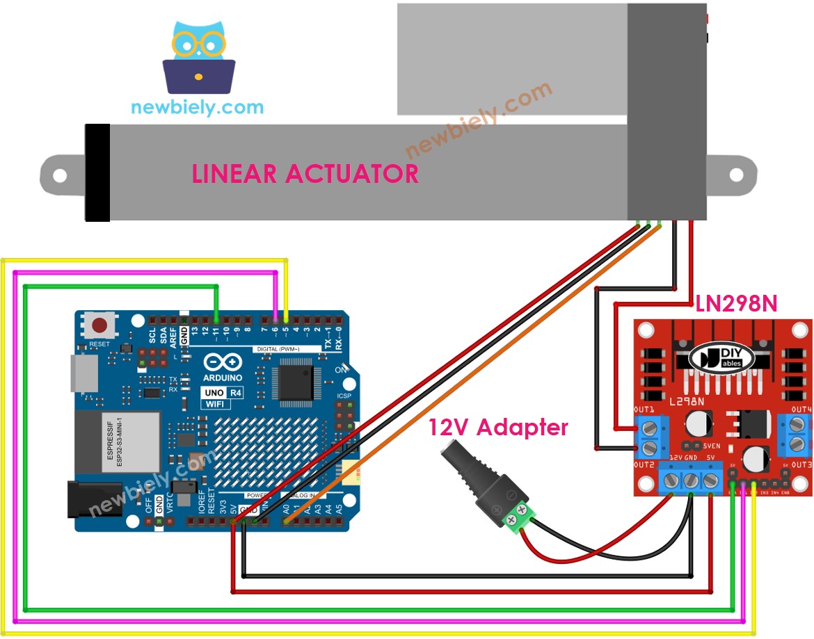
This image is created using Fritzing. Click to enlarge image

See The best way to supply power to the Arduino Uno R4 and other components.

How to control extend/retract a linear actuator

Visit the tutorial for the Arduino UNO R4 Actuator here.

How to find the position of the linear actuator

Here's how to find the stroke position on a linear actuator:

Calibration

  • Measure the length of the actuator's stroke (in millimeters) with a ruler or check the datasheet.
  • Find the output values when the linear actuator is fully extended and retracted by executing the following code.
/* * This Arduino UNO R4 code was developed by newbiely.com * * This Arduino UNO R4 code is made available for public use without any restriction * * For comprehensive instructions and wiring diagrams, please visit: * https://newbiely.com/tutorials/arduino-uno-r4/arduino-uno-r4-actuator-with-feedback */ // the code for getting the feedback when the actuator fully extended and retracted #define ENA_PIN 11 // The Arduino Uno R4 pin connected to the EN1 pin L298N #define IN1_PIN 6 // The Arduino Uno R4 pin connected to the IN1 pin L298N #define IN2_PIN 5 // The Arduino Uno R4 pin connected to the IN2 pin L298N #define POTENTIOMETER_PIN A0 // The Arduino Uno R4 pin connected to the potentiometer of the actuator void setup() { Serial.begin(9600); // initialize digital pins as outputs. pinMode(ENA_PIN, OUTPUT); pinMode(IN1_PIN, OUTPUT); pinMode(IN2_PIN, OUTPUT); digitalWrite(ENA_PIN, HIGH); } void loop() { // extend the actuator digitalWrite(IN1_PIN, HIGH); digitalWrite(IN2_PIN, LOW); delay(20000); // wait for actuator fully extends. It will stop extending automatically when reaching the limit // read the analog in value: int POTENTIOMETER_MAX = analogRead(POTENTIOMETER_PIN); Serial.print("POTENTIOMETER_MAX = "); Serial.println(POTENTIOMETER_MAX); // retracts the actuator digitalWrite(IN1_PIN, LOW); digitalWrite(IN2_PIN, HIGH); delay(20000); // wait for actuator fully extends. It will stop retracting automatically when reaching the limit int POTENTIOMETER_MIN = analogRead(POTENTIOMETER_PIN); Serial.print("POTENTIOMETER_MIN = "); Serial.println(POTENTIOMETER_MIN); }
  • You will see the log on the Serial Monitor as shown in the example below.
COM6
Send
POTENTIOMETER_MAX = 987 POTENTIOMETER_MIN = 13
Autoscroll Show timestamp
Clear output
9600 baud  
Newline  
  • Write down these values.
  • If the minimum and maximum values are reversed, switch IN1_PIN with IN2_PIN.
  • Update three values in the code below.

Arduino UNO R4 code that calculate the position of the actuator

/* * This Arduino UNO R4 code was developed by newbiely.com * * This Arduino UNO R4 code is made available for public use without any restriction * * For comprehensive instructions and wiring diagrams, please visit: * https://newbiely.com/tutorials/arduino-uno-r4/arduino-uno-r4-actuator-with-feedback */ #define ENA_PIN 11 // The Arduino Uno R4 pin connected to the EN1 pin L298N #define IN1_PIN 6 // The Arduino Uno R4 pin connected to the IN1 pin L298N #define IN2_PIN 5 // The Arduino Uno R4 pin connected to the IN2 pin L298N #define POTENTIOMETER_PIN A0 // The Arduino Uno R4 pin connected to the potentiometer of the actuator #define STROKE_LENGTH 102 // PLEASE UPDATE THIS VALUE (in millimeter) #define POTENTIOMETER_MAX 987 // PLEASE UPDATE THIS VALUE #define POTENTIOMETER_MIN 13 // PLEASE UPDATE THIS VALUE void setup() { Serial.begin(9600); // initialize digital pins as outputs. pinMode(ENA_PIN, OUTPUT); pinMode(IN1_PIN, OUTPUT); pinMode(IN2_PIN, OUTPUT); digitalWrite(ENA_PIN, HIGH); } void loop() { // extend the actuator digitalWrite(IN1_PIN, HIGH); digitalWrite(IN2_PIN, LOW); int potentiometer_value = analogRead(POTENTIOMETER_PIN); int stroke_pos = map(potentiometer_value, POTENTIOMETER_MIN, POTENTIOMETER_MAX, 0, STROKE_LENGTH); Serial.print("The stroke's position = "); Serial.print(stroke_pos); Serial.println(" mm"); }
  • Change the three adjusted values in the code
  • Load the code onto Arduino UNO R4
  • Check the outcome on the Serial Monitor
COM6
Send
The stroke's position = 2 mm The stroke's position = 35 mm The stroke's position = 43 mm The stroke's position = 60 mm The stroke's position = 68 mm The stroke's position = 79 mm The stroke's position = 83 mm The stroke's position = 96 mm The stroke's position = 100 mm
Autoscroll Show timestamp
Clear output
9600 baud  
Newline  

How to control a linear actuator to a specific position

/* * This Arduino UNO R4 code was developed by newbiely.com * * This Arduino UNO R4 code is made available for public use without any restriction * * For comprehensive instructions and wiring diagrams, please visit: * https://newbiely.com/tutorials/arduino-uno-r4/arduino-uno-r4-actuator-with-feedback */ #define ENA_PIN 11 // The Arduino Uno R4 pin connected to the EN1 pin L298N #define IN1_PIN 6 // The Arduino Uno R4 pin connected to the IN1 pin L298N #define IN2_PIN 5 // The Arduino Uno R4 pin connected to the IN2 pin L298N #define POTENTIOMETER_PIN A0 // The Arduino Uno R4 pin connected to the potentiometer of the actuator #define STROKE_LENGTH 102 // PLEASE UPDATE THIS VALUE (in millimeter) #define POTENTIOMETER_MAX 987 // PLEASE UPDATE THIS VALUE #define POTENTIOMETER_MIN 13 // PLEASE UPDATE THIS VALUE #define TOLERANCE 5 // in millimeter int targetPosition_mm = 50; // in millimeter void setup() { Serial.begin(9600); // initialize digital pins as outputs. pinMode(ENA_PIN, OUTPUT); pinMode(IN1_PIN, OUTPUT); pinMode(IN2_PIN, OUTPUT); digitalWrite(ENA_PIN, HIGH); } void loop() { int potentiometer_value = analogRead(POTENTIOMETER_PIN); int stroke_pos = map(potentiometer_value, POTENTIOMETER_MIN, POTENTIOMETER_MAX, 0, STROKE_LENGTH); Serial.print("The stroke's position = "); Serial.print(stroke_pos); Serial.println(" mm"); if (stroke_pos < (targetPosition_mm - TOLERANCE)) ACTUATOR_extend(); else if (stroke_pos > (targetPosition_mm + TOLERANCE)) ACTUATOR_retract(); else ACTUATOR_stop(); } void ACTUATOR_extend() { digitalWrite(IN1_PIN, HIGH); digitalWrite(IN2_PIN, LOW); } void ACTUATOR_retract() { digitalWrite(IN1_PIN, LOW); digitalWrite(IN2_PIN, HIGH); } void ACTUATOR_stop() { digitalWrite(IN1_PIN, LOW); digitalWrite(IN2_PIN, LOW); }

Video Tutorial

Summary

In this Arduino UNO R4 tutorial, you learned how to use a feedback linear actuator for DIY projects. This easy guide taught you how the actuator works, how to find its position in millimeters, and how to move it to the right spot with Arduino programming. After our lesson on a linear actuator without feedback, this simple Arduino project shows you how to make a smart moving system. Now you can build your own movement control projects with Arduino UNO R4!

※ OUR MESSAGES

  • As freelancers, We are AVAILABLE for HIRE. See how to outsource your project to us
  • Please feel free to share the link of this tutorial. However, Please do not use our content on any other websites. We invested a lot of effort and time to create the content, please respect our work!