Arduino UNO R4 - DIP Switch
DIP (Dual In-line Package) switches are often used in electronics to set up devices, like setting addresses or turning features on and off. In this guide, we will learn how to use a DIP switch with Arduino UNO R4. We will cover:
- A DIP switch is a small device used to control electronic circuits. It has several switches that you can turn on or off to change settings.
- To connect a DIP switch to an Arduino UNO R3, connect one side of the switches to Arduino's digital pins and the other side to the ground.
- To make the Arduino read whether the DIP switches are on or off, set up digital pins as inputs in your program. Use digitalRead() function to check the state of each switch.
- To have the Arduino read a number set by the DIP switches, treat each switch as a binary digit. Combine their on/off states to form a binary number, then convert it to a decimal integer to use in your program.
Hardware Preparation
Or you can buy the following kits:
| 1 | × | DIYables STEM V4 IoT Starter Kit (Arduino included) | |
| 1 | × | DIYables Sensor Kit (18 sensors/displays) |
Additionally, some of these links are for products from our own brand, DIYables .

Overview of DIP Switch
DIP switches are mainly used to configure devices, letting users adjust settings like device address, communication options, security codes, operation mode, and system preferences for different uses and industries.
A DIP switch consists of multiple tiny slide switches combined into one unit. Each slide switch is called a "position". There are different kinds of DIP switches, each with a specific number of positions such as 2, 4, 5, 6, 8, or 10.
A DIP switch can be set to represent different numbers. Each switch position connects to a bit in the number. By switching these positions ON or OFF, we can choose the number we need.
Pinout
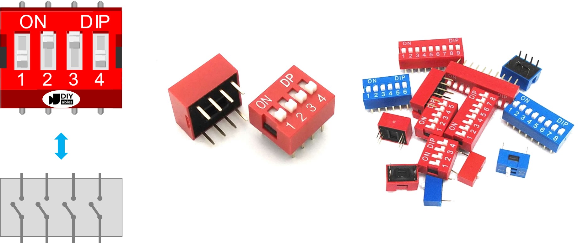
A DIP switch has two rows of pins. The number of pins in each row matches the number of switch positions. For example, in a DIP switch with 4 positions, there are 8 pins total, with 4 pins on each side. Each pair of pins across from each other forms a slide switch. It's important to note that it doesn't matter which side a pin is on because the pins are interchangeable.
How It Works
When a DIP switch is ON, it is closed. This allows electricity to flow through the switch.
When a switch is OFF, it is open. This means the electrical connection is broken and no current can flow through the switch.
To make it clear:
- ON position: Circuit is closed, current can pass.
- OFF position: Circuit is open, current cannot pass.
When you connect one side of the switch to GND and the other side to the Arduino UNO R4 pin, and set the Arduino UNO R4 pin as a pull-up digital input, the table below shows the relationship between the switch position and the values read from the Arduino UNO R4.
| DIP switch position | Binary representation | Circuit state | Arduino UNO R4 pin state |
|---|---|---|---|
| ON | 1 | CLOSED | LOW |
| OFF | 0 | OPEN | HIGH |
In the following sections, we will use a 4-position DIP switch as an example. You can also adjust this for 2-position, 3-position, 5-position, 6-position, 8-position, and 10-position DIP switches.
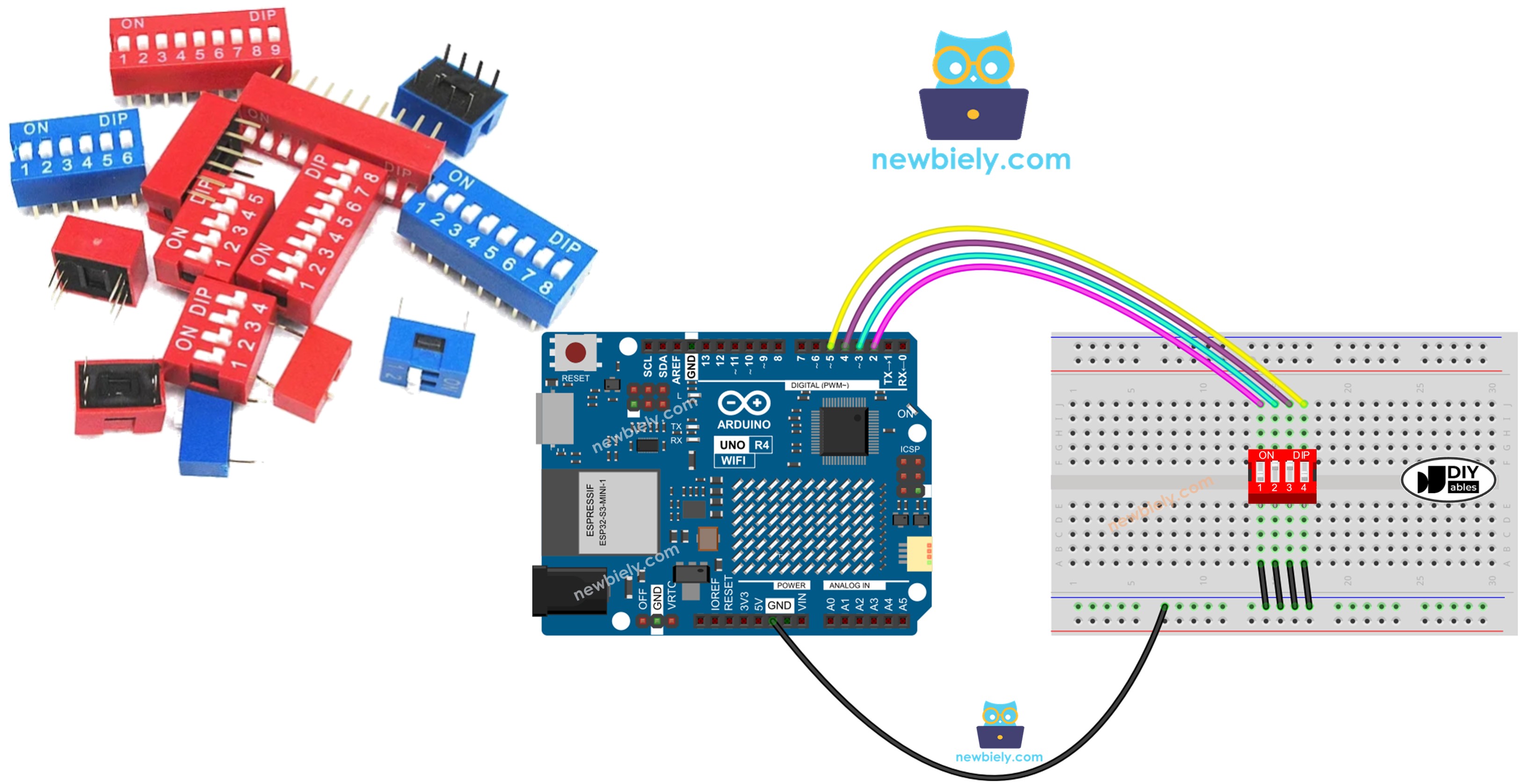
Wiring Diagram
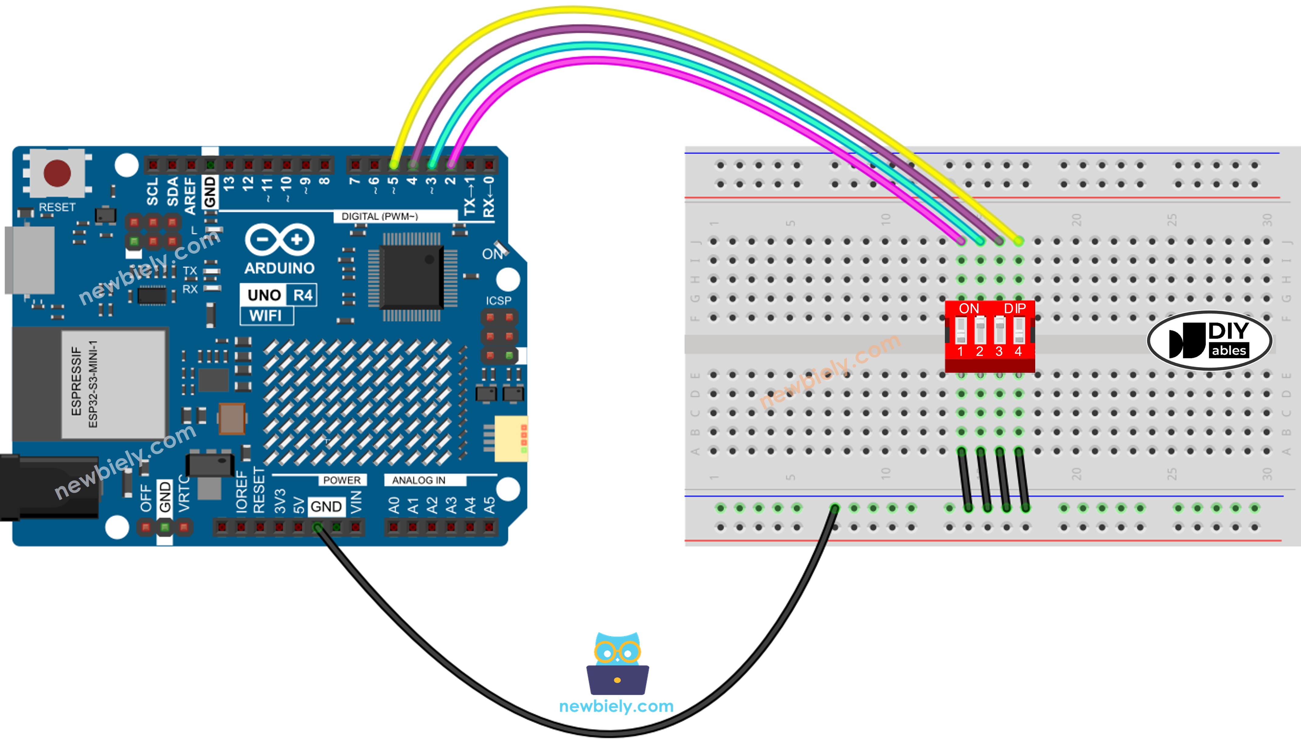
This image is created using Fritzing. Click to enlarge image
See The best way to supply power to the Arduino Uno R4 and other components.
Arduino UNO R4 Code - DIP Switch
We will explore using two code examples:
- Checking if each switch is ON or OFF.
- Turning these switch positions into a number.
Arduino UNO R4 code - Reading the ON/OFF state of the DIP switch
Detailed Instructions
Follow these instructions step by step:
- If this is your first time using the Arduino Uno R4 WiFi/Minima, refer to the tutorial on setting up the environment for Arduino Uno R4 WiFi/Minima in the Arduino IDE.
- Wire the components according to the provided diagram.
- Connect the Arduino Uno R4 board to your computer using a USB cable.
- Launch the Arduino IDE on your computer.
- Select the appropriate Arduino Uno R4 board (e.g., Arduino Uno R4 WiFi) and COM port.
- Follow the wiring diagram provided.
- Connect the Arduino UNO R4 to your computer using a USB cable.
- Launch the Arduino IDE software.
- Choose the correct board and port.
- Click the Upload button in the Arduino IDE to send the code to the Arduino UNO R4.
- Turn on each switch of the DIP Switch one at a time.
- Check the results on the Serial Monitor.
Arduino UNO R4 code - Encoding the states of DIP switch into a number
Detailed Instructions
Follow these instructions step by step:
- If this is your first time using the Arduino Uno R4 WiFi/Minima, refer to the tutorial on setting up the environment for Arduino Uno R4 WiFi/Minima in the Arduino IDE.
- Wire the components according to the provided diagram.
- Connect the Arduino Uno R4 board to your computer using a USB cable.
- Launch the Arduino IDE on your computer.
- Select the appropriate Arduino Uno R4 board (e.g., Arduino Uno R4 WiFi) and COM port.
- Upload the code to Arduino UNO R4.
- Turn on each switch on the DIP switch one at a time.
- Check the Serial Monitor to see the results, which will appear as follows.
Be aware that the value changes based on the positions of each slide switch. The table below displays how the ON/OFF positions correspond to the integer values for a 4-position DIP switch:
| Position-1 | Position-2 | Position-3 | Position-4 | Binary Value | Decimal Value |
|---|---|---|---|---|---|
| OFF | OFF | OFF | OFF | 0000 | 0 |
| OFF | OFF | OFF | ON | 0001 | 1 |
| OFF | OFF | ON | OFF | 0010 | 2 |
| OFF | OFF | ON | ON | 0011 | 3 |
| OFF | ON | OFF | OFF | 0100 | 4 |
| OFF | ON | OFF | ON | 0101 | 5 |
| OFF | ON | ON | OFF | 0110 | 6 |
| OFF | ON | ON | ON | 0111 | 7 |
| ON | OFF | OFF | OFF | 1000 | 8 |
| ON | OFF | OFF | ON | 1001 | 9 |
| ON | OFF | ON | OFF | 1010 | 10 |
| ON | OFF | ON | ON | 1011 | 11 |
| ON | ON | OFF | OFF | 1100 | 12 |
| ON | ON | OFF | ON | 1101 | 13 |
| ON | ON | ON | OFF | 1110 | 14 |
| ON | ON | ON | ON | 1111 | 15 |