Arduino UNO R4 - Light Sensor Control LED
In this guide, we will learn how to:
- Turn the LED on if the light sensor's analog value is below a threshold.
- Turn the LED off if the light sensor's analog value is above a threshold.
Hardware Preparation
Or you can buy the following kits:
| 1 | × | DIYables STEM V4 IoT Starter Kit (Arduino included) | |
| 1 | × | DIYables Sensor Kit (18 sensors/displays) |
Disclosure: Some of the links provided in this section are Amazon affiliate links. We may receive a commission for any purchases made through these links at no additional cost to you.
Additionally, some of these links are for products from our own brand, DIYables .
Additionally, some of these links are for products from our own brand, DIYables .
Buy Note: Use the LED Module for easier wiring. It includes an integrated resistor.

The LDR light sensor is very affordable, but it requires a resistor for wiring, which can make the setup more complex. To simplify the wiring, you can use an LDR light sensor module as an alternative.
Overview of LED and Light Sensor
Learn about LED and light sensors (pinout, their functions, and programming) in the tutorials below:
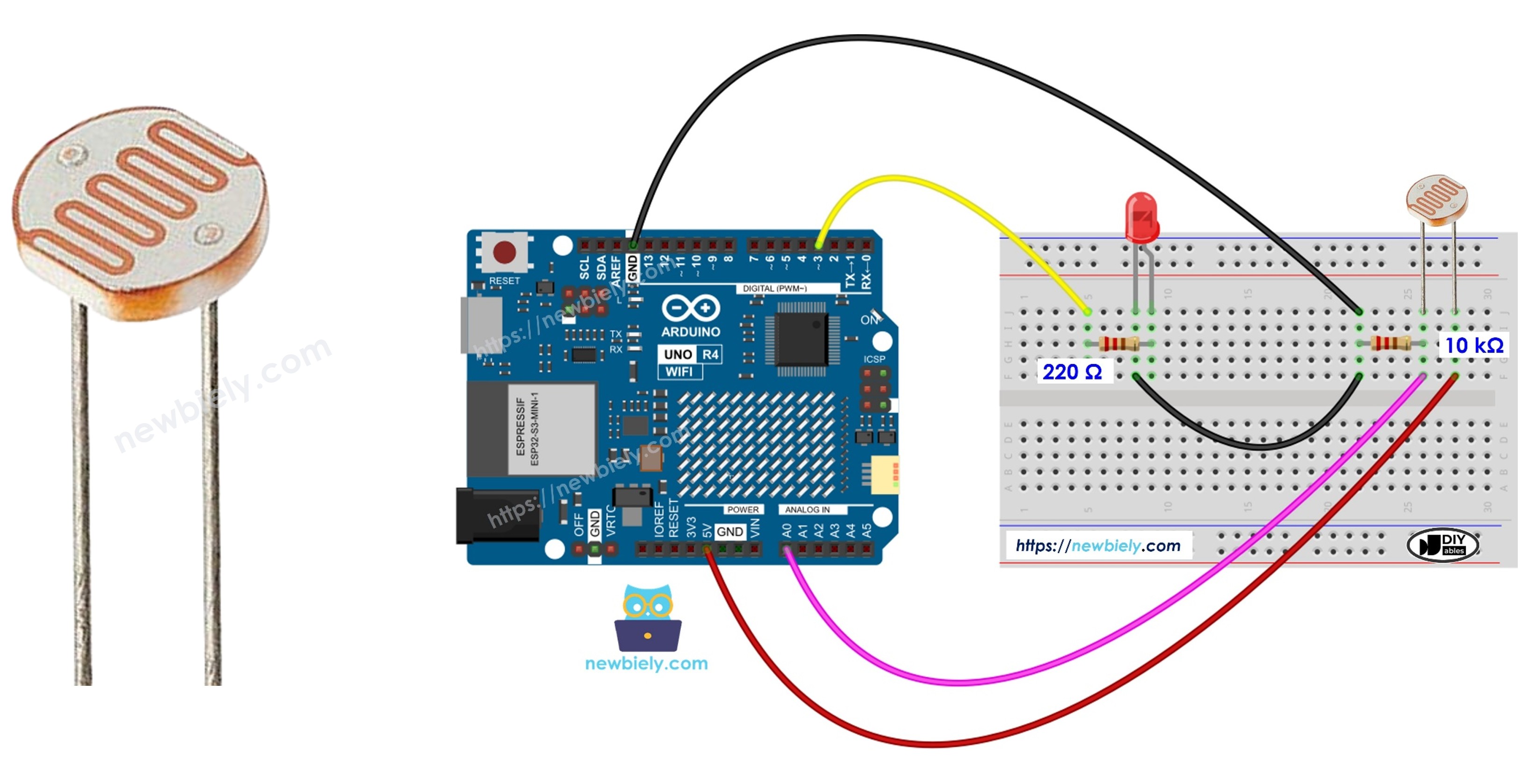
Wiring Diagram
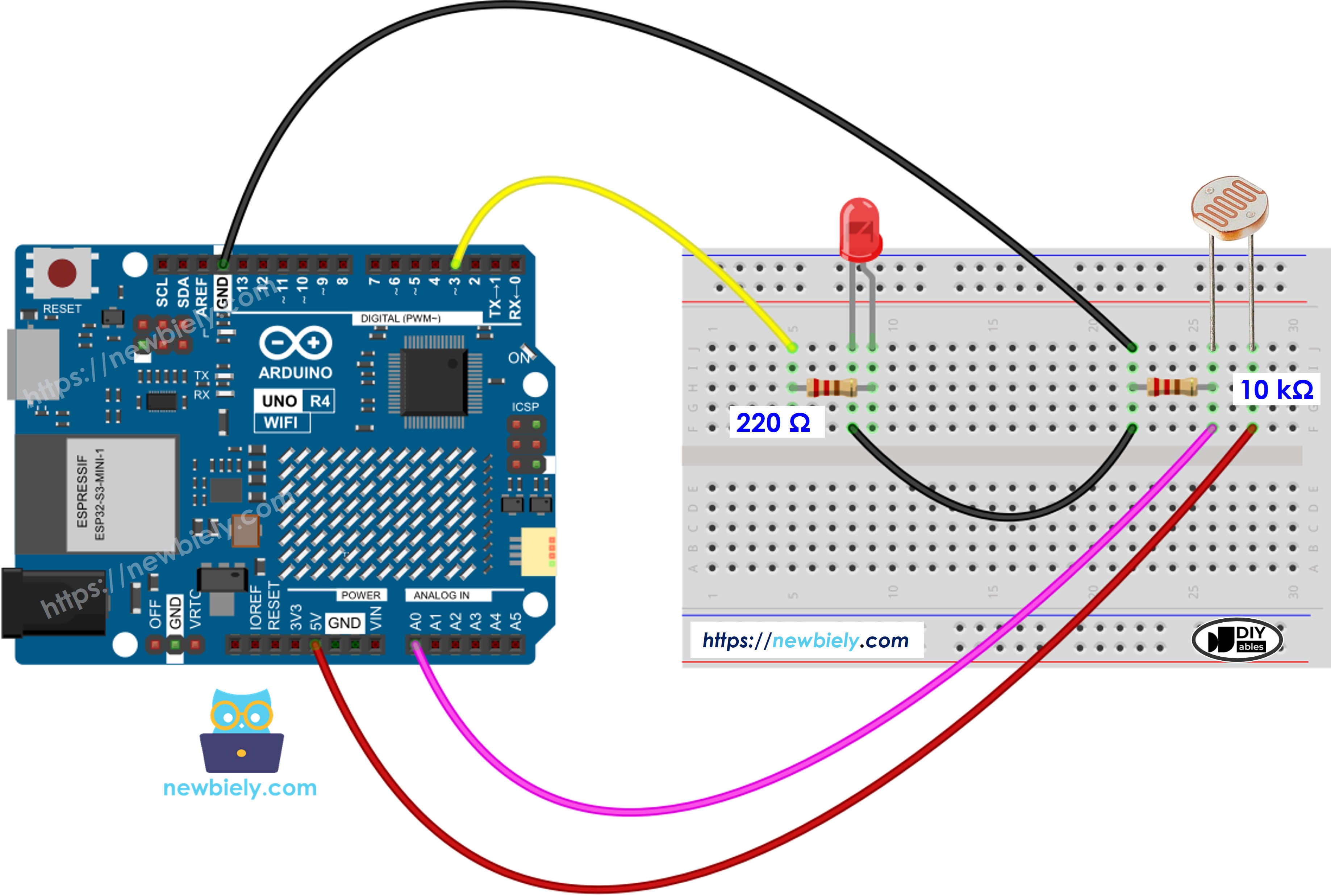
This image is created using Fritzing. Click to enlarge image
See The best way to supply power to the Arduino Uno R4 and other components.
Arduino UNO R4 Code
/*
* This Arduino UNO R4 code was developed by newbiely.com
*
* This Arduino UNO R4 code is made available for public use without any restriction
*
* For comprehensive instructions and wiring diagrams, please visit:
* https://newbiely.com/tutorials/arduino-uno-r4/arduino-uno-r4-light-sensor-controls-led
*/
#define LIGHT_SENSOR_PIN A0 // Arduino Uno R4 pin connected to light sensor's pin
#define LED_PIN 3 // Arduino Uno R4 pin connected to LED's pin
#define ANALOG_THRESHOLD 50
// variables will change:
int analogValue;
void setup() {
pinMode(LED_PIN, OUTPUT); // set arduino pin to output mode
}
void loop() {
analogValue = analogRead(LIGHT_SENSOR_PIN); // read the input on analog pin
if(analogValue < ANALOG_THRESHOLD)
digitalWrite(LED_PIN, HIGH); // turn on LED
else
digitalWrite(LED_PIN, LOW); // turn off LED
}
Detailed Instructions
Follow these instructions step by step:
- If this is your first time using the Arduino Uno R4 WiFi/Minima, refer to the tutorial on setting up the environment for Arduino Uno R4 WiFi/Minima in the Arduino IDE.
- Wire the components according to the provided diagram.
- Connect the Arduino Uno R4 board to your computer using a USB cable.
- Launch the Arduino IDE on your computer.
- Select the appropriate Arduino Uno R4 board (e.g., Arduino Uno R4 WiFi) and COM port.
- Connect the Arduino UNO R4 to your computer using a USB cable.
- Open the Arduino IDE, and choose the correct board and port.
- Copy the code provided and paste it into the Arduino IDE.
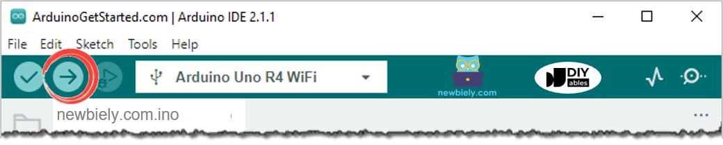
- Press the Upload button in the Arduino IDE to transfer the code to the Arduino UNO R4.
- Shines light on sensor
- Observe the change in the LED's state
Code Explanation
Check the explanation provided in the comments within the source code!