
ESP32 S3 - LCD
This tutorial shows you how to use an LCD I2C display with your ESP32 S3 board. You will learn to display text, special characters, and create interactive projects using this popular LCD module with the powerful ESP32 S3.
What you'll build:
- A working LCD I2C display connected to your ESP32 S3
- A sketch that alternates between two custom messages on screen
- A foundation for cursor positioning and text printing
- A launchpad for real-world LCD-based projects
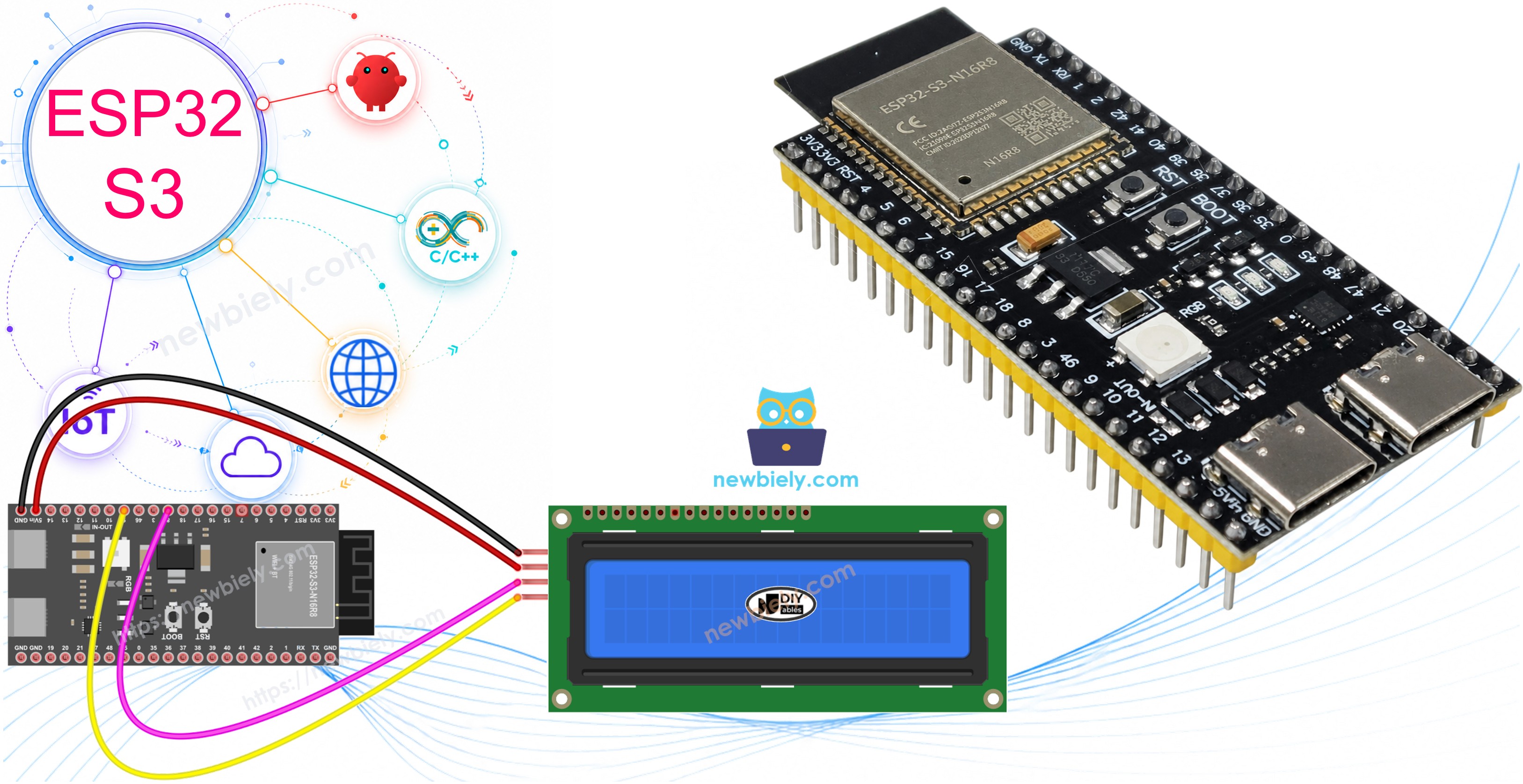
Hardware Preparation
Or you can buy the following kits:
| 1 | × | DIYables ESP32 S3 Starter Kit (ESP32 S3 included) | |
| 1 | × | DIYables Sensor Kit (18 sensors/displays) |
Additionally, some of these links are for products from our own brand, DIYables .
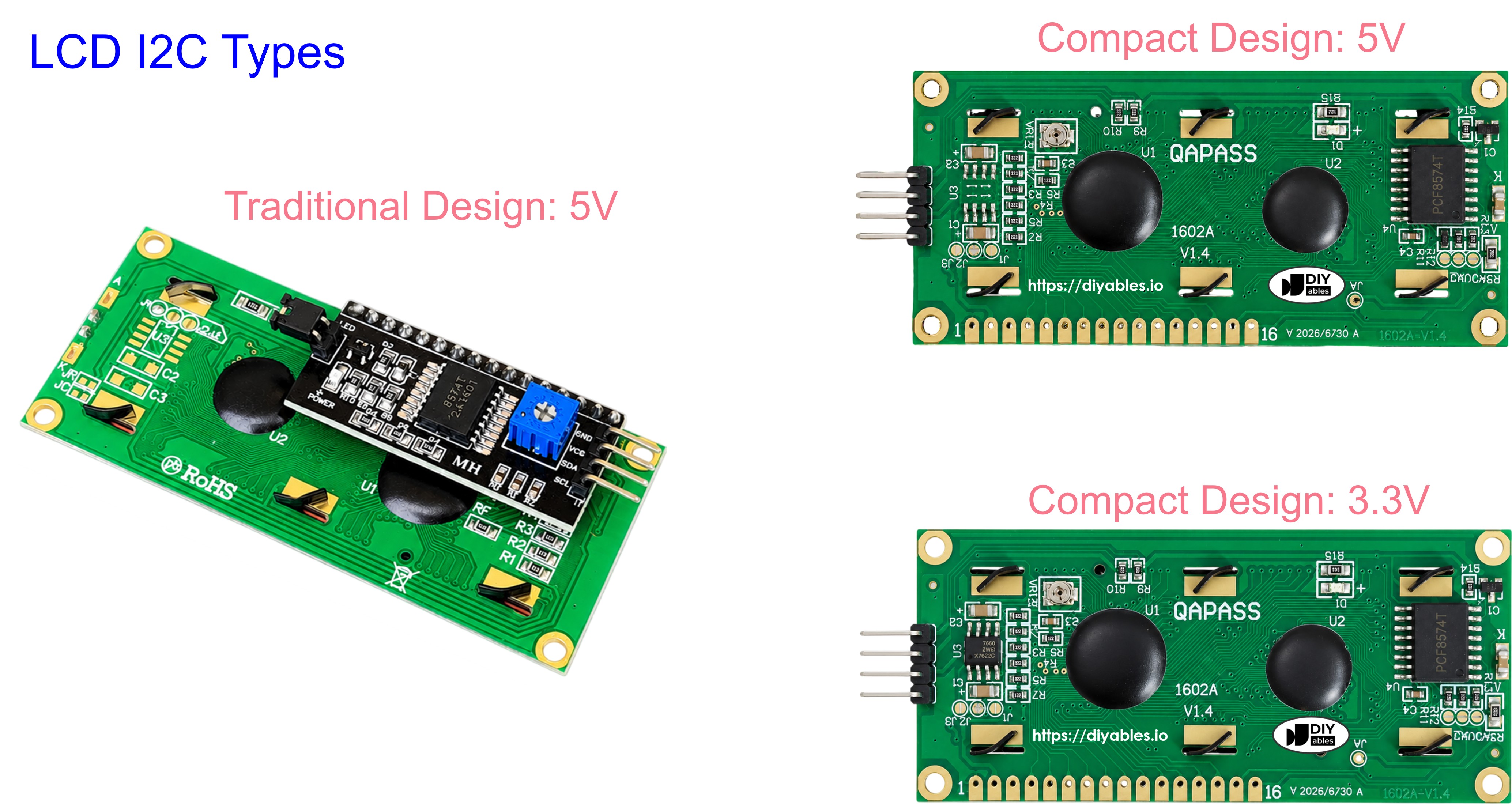
Buy Note: Most LCD I2C displays available on the market are 5V displays. They may work with this board, but it is unsafe and can damage the board. We strongly recommend using the 3.3V LCD I2C display recommended above.
Overview of LCD I2C 16x2
LCD I2C is a liquid crystal display module that uses the I2C communication protocol to simplify wiring and save GPIO pins on your ESP32 S3. The I2C interface reduces the connection from more than a dozen parallel wires down to just four, making it ideal for projects where pin count matters. An onboard PCF8574 I/O expander handles the translation between I2C commands and the LCD's native parallel interface, so your code remains clean and straightforward.
Key Specifications
The LCD I2C 16x2 offers a 16-column by 2-row character display with a built-in backlight for better visibility in low-light environments. It operates at a 5V power supply and communicates at the standard I2C address of 0x27 or 0x3F depending on the manufacturer. Contrast can be fine-tuned via a small potentiometer on the back of the module, and up to eight user-defined custom characters are supported alongside the standard ASCII set.
LCD I2C Pinout
The LCD I2C module exposes four pins for a straightforward connection to any I2C-capable microcontroller:
- VCC: Power supply pin — connect to 5V
- GND: Ground pin — connect to GND (0V)
- SCL: I2C clock signal pin for communication
- SDA: I2C data signal pin for communication
LCD 16x2 Coordinates
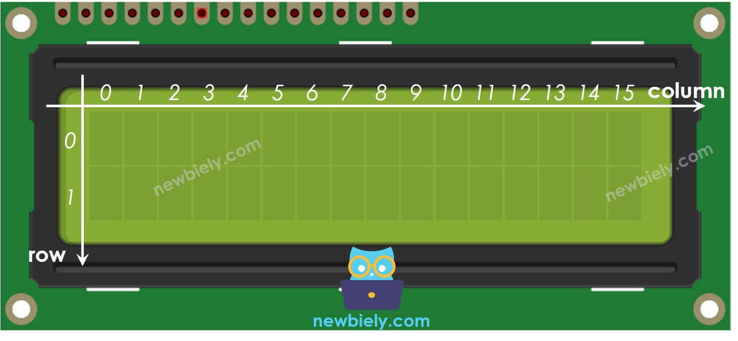
LCD I2C 16x2 has 2 rows and 16 columns indexed from 0.
The display uses a simple column-row coordinate system where columns run from 0 to 15 (left to right) and rows run from 0 to 1 (top to bottom). The top-left corner is position (0, 0) and the bottom-right corner is position (15, 1). Use setCursor(column, row) in your sketch to place the cursor at any position before printing text.
Wiring Diagram between LCD I2C and ESP32 S3
Connect your LCD I2C display to the ESP32 S3 using the board's I2C pins as shown below. The LCD requires 5V to operate, so you have two power options depending on how you are powering your ESP32 S3.
Safety Notes
Always make sure the power supply to the LCD is stable at 5V before powering up the circuit. When using USB power, the VBUS pin provides 5V directly from the USB host, which is usually sufficient, but some USB ports may not supply enough current — if the display flickers or shows garbled text, switch to an external 5V supply connected to the Vin pin and shared GND. Never connect the LCD's VCC pin to 3.3V as this will prevent the backlight and display from working correctly.
Wiring diagram when powering via USB:
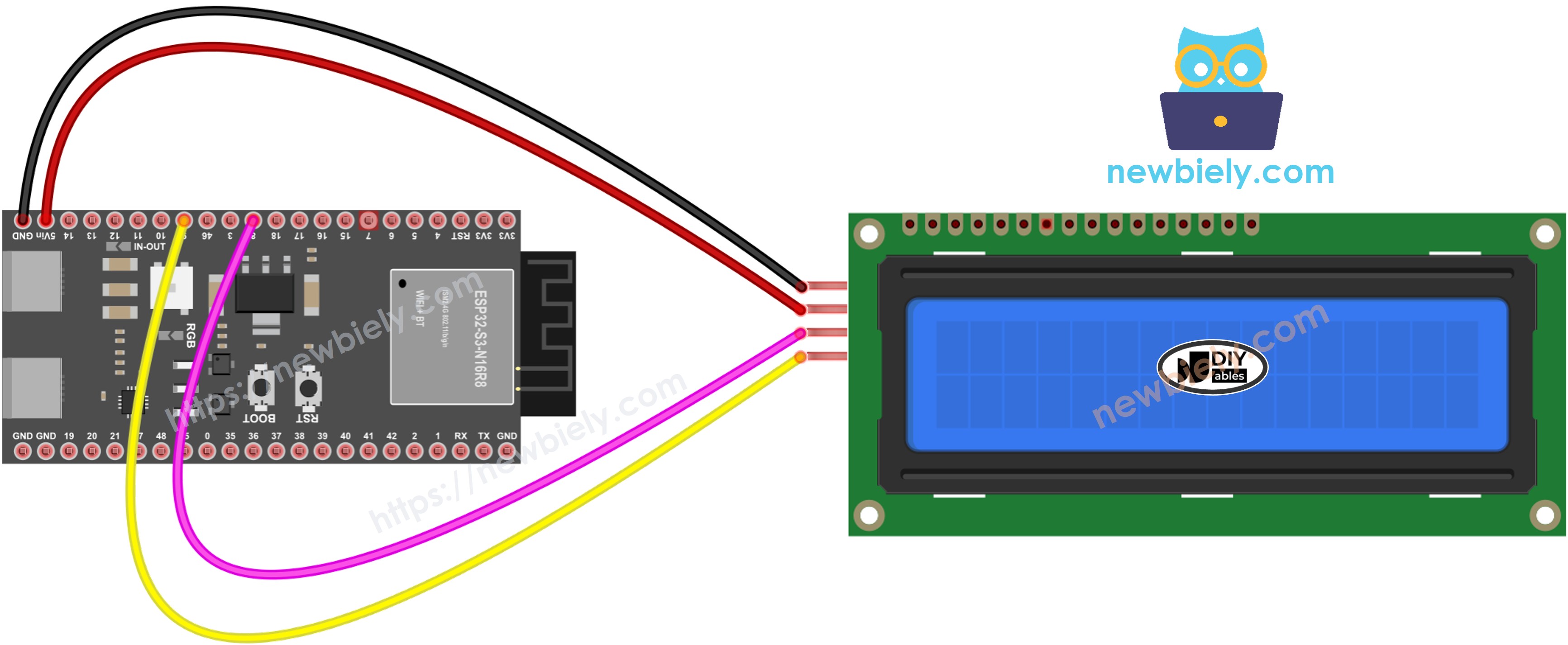
This image is created using Fritzing. Click to enlarge image
| LCD I2C Pin | ESP32 S3 Pin |
|---|---|
| VCC | VBUS (5V) |
| GND | GND |
| SCL | GPIO9 (I2C Clock) |
| SDA | GPIO8 (I2C Data) |
Wiring diagram when powering via Vin pin:
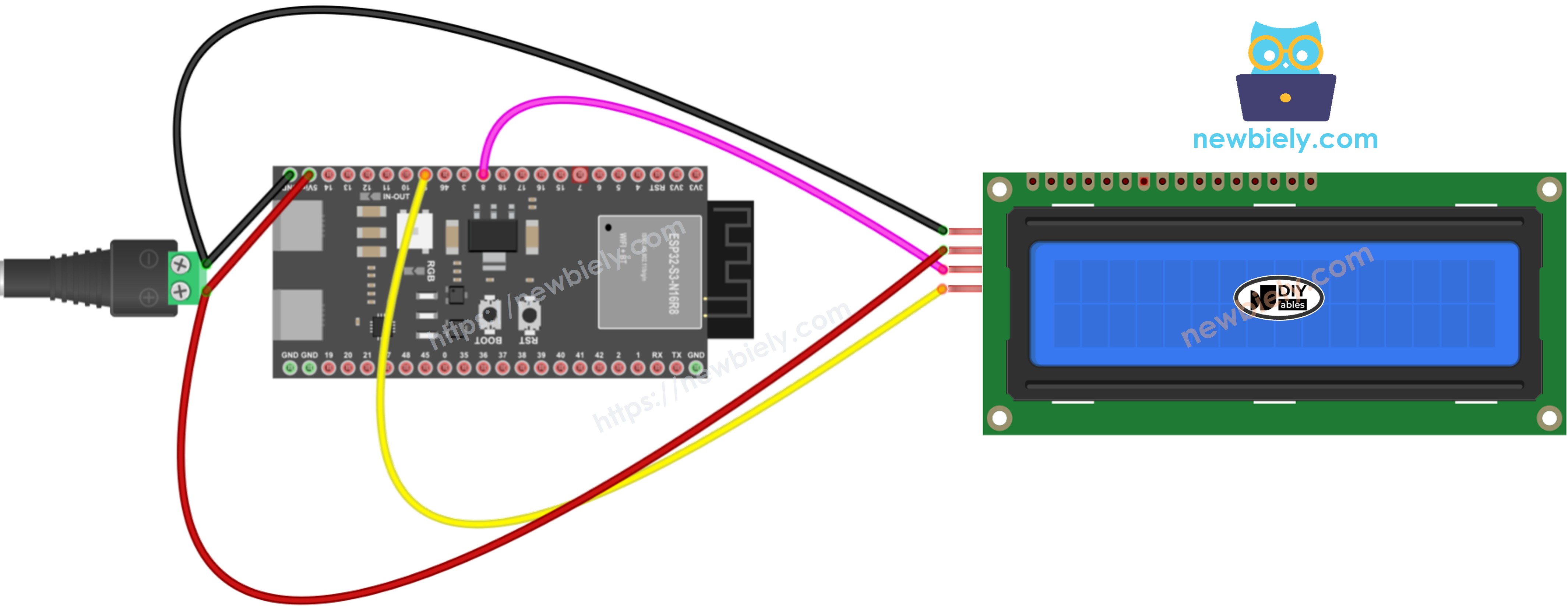
This image is created using Fritzing. Click to enlarge image
| LCD I2C Pin | ESP32 S3 Pin |
|---|---|
| VCC | External 5V Power Source |
| GND | GND (shared with ESP32) |
| SCL | GPIO9 (I2C Clock) |
| SDA | GPIO8 (I2C Data) |
※ NOTE THAT:
When powering the ESP32 S3 through the USB port, it is possible to power the LCD display using the VBUS pin of the ESP32 S3, eliminating the need for an external power source. However, it is important to note that this approach may not work as the power provided by the VBUS pin might be insufficient for the proper functioning of the LCD display.
How To Program LCD I2C using ESP32 S3
Programming the LCD I2C with the ESP32 S3 is straightforward thanks to the DIYables LCD I2C library, which wraps all low-level I2C communication into a clean API. The library provides methods for initializing the display, controlling the backlight, positioning the cursor, and printing text or custom characters. The steps below walk through each building block you need before assembling the full sketch.
Include the DIYables LCD I2C library:
Declare a DIYables_LCD_I2C object:
Initialize the LCD in setup():
Move cursor to desired position:
Print text to the LCD:
Clear the display:
※ NOTE THAT:
The LCD I2C address can be different from each manufacturer. In the code, we used address of 0x27 that is specified by DIYables manufacturer. If your LCD doesn't work, try address 0x3F instead.
ESP32 S3 Code
The following code demonstrates a complete working example that alternates between two messages on the LCD I2C 16x2 display. It initializes the display with the backlight enabled, prints the first pair of messages for two seconds, then clears the screen and prints a second pair of messages for another two seconds before repeating the cycle. This pattern is a solid foundation for any project that needs to cycle through status screens or display dynamic data.
Detailed Instructions
- New to ESP32 S3? Complete our Getting Started with ESP32 S3 guide first.
- Open Library Manager: Click on the Library Manager icon on the left navigation bar of Arduino IDE.
- Search for library: Type "DIYables LCD I2C" in the search box.
- Install library: Look for the DIYables_LCD_I2C library by DIYables and click the Install button.
- Search for DIYables LCD I2C created by DIYables.io and click the Install button.
- Copy the code: Copy the code above and paste it into Arduino IDE.
- Connect your board: Plug your ESP32 S3 into your computer via USB Type-C cable.
- Select board and port: Choose the correct board and COM port in Arduino IDE.
- Upload the code: Click the Upload button to compile and upload the code to your ESP32 S3.
- View the results: Watch the text alternate between the two messages on your LCD screen.
- Experiment: Try modifying the text, cursor positions, and delay times to customize your display.
- Pro Tip: If the text is invisible or faint, adjust the small potentiometer on the back of the LCD module to increase contrast until the characters are clearly visible.
Do More with LCD
Custom Character
Want to display emoticons, degree symbols, or other special characters on your LCD I2C display? The LCD I2C 16x2 supports up to eight custom characters, each defined as a 5x8 pixel bitmap stored in a byte array. Custom characters are great for icons such as a temperature degree symbol, heart icon, battery level bar, or simple progress indicator. See how to display special characters on LCD for detailed instructions and ready-to-use bitmap arrays.
Application Ideas for ESP32 S3 LCD I2C Projects
The combination of the ESP32 S3's processing power and wireless connectivity with the simplicity of an LCD I2C display opens the door to a wide range of practical projects.
- Temperature monitor: Display real-time temperature and humidity readings from a DHT or BME sensor on the LCD screen.
- Real-time clock: Show current date and time fetched from an NTP server over WiFi with automatic timezone handling.
- Countdown timer: Build a kitchen or tutorial timer with start, pause, and reset controls via push buttons.
- Menu system: Create a multi-level menu for configuring project settings using button navigation and LCD feedback.
- WiFi status display: Show SSID, IP address, and signal strength so you always know the network connection state.
- Scrolling message board: Scroll long messages or announcements across the 16-column display in a loop.
- Smart home panel: Display the status of multiple smart home devices or sensor readings on a single compact screen.
Troubleshooting on LCD I2C
If your LCD I2C doesn't display anything, check these common issues:
- Blank screen: Check if backlight is enabled with lcd_i2c.backlight()
- No text visible: Adjust the contrast potentiometer on the back of LCD module
- Nothing displays: Try I2C address 0x3F instead of 0x27 in code
- Wiring issues: Verify SCL and SDA connections to correct GPIO pins
- Power problems: Ensure LCD is receiving 5V (use external power if USB insufficient)
- Library errors: Confirm DIYables_LCD_I2C library is properly installed
For a complete troubleshooting checklist, see LCD does not work! - Checklist
Video Tutorial
Watch the step-by-step video walkthrough for this ESP32 S3 project below.
Challenge Yourself
Once you have the basic LCD working, these challenges will push your skills further with progressively more complex tasks.
- Beginner: Create a counter that increments from 0 to 99 on the top row and resets automatically, updating once per second.
- Beginner: Display your name scrolling smoothly across the screen from right to left using a loop and setCursor.
- Intermediate: Add a DHT11 sensor and display live temperature and humidity readings on separate rows, refreshing every two seconds.
- Intermediate: Build a two-option menu system controlled by two push buttons, highlighting the selected option on the LCD.
- Advanced: Connect to WiFi and display the current time fetched from an NTP server, with automatic daylight saving adjustment.
- Advanced: Design a set of five custom bitmap characters and create an animated sequence that plays on the LCD in a loop.