
ESP32 S3 - Control Pump
Learn how to control a 12V water pump with the ESP32 S3 using a relay module. This tutorial covers everything from wiring and code to automating pump control for your DIY projects.
You can drive the pump through a relay module or through a MOSFET module. The relay simply starts and stops the pump. The MOSFET module can start and stop it too, and on top of that it can change the pump speed, so you decide how much water flows. It also works silently. You will try both in this tutorial.
What you'll build:
- A circuit connecting the ESP32 S3, relay module, and 12V pump
- A sketch that toggles the pump on and off every 4 seconds
- Serial Monitor output confirming pump state in real time
- A foundation for aquarium, irrigation, or cocktail machine automation
- A MOSFET module circuit that raises and lowers the water flow with PWM
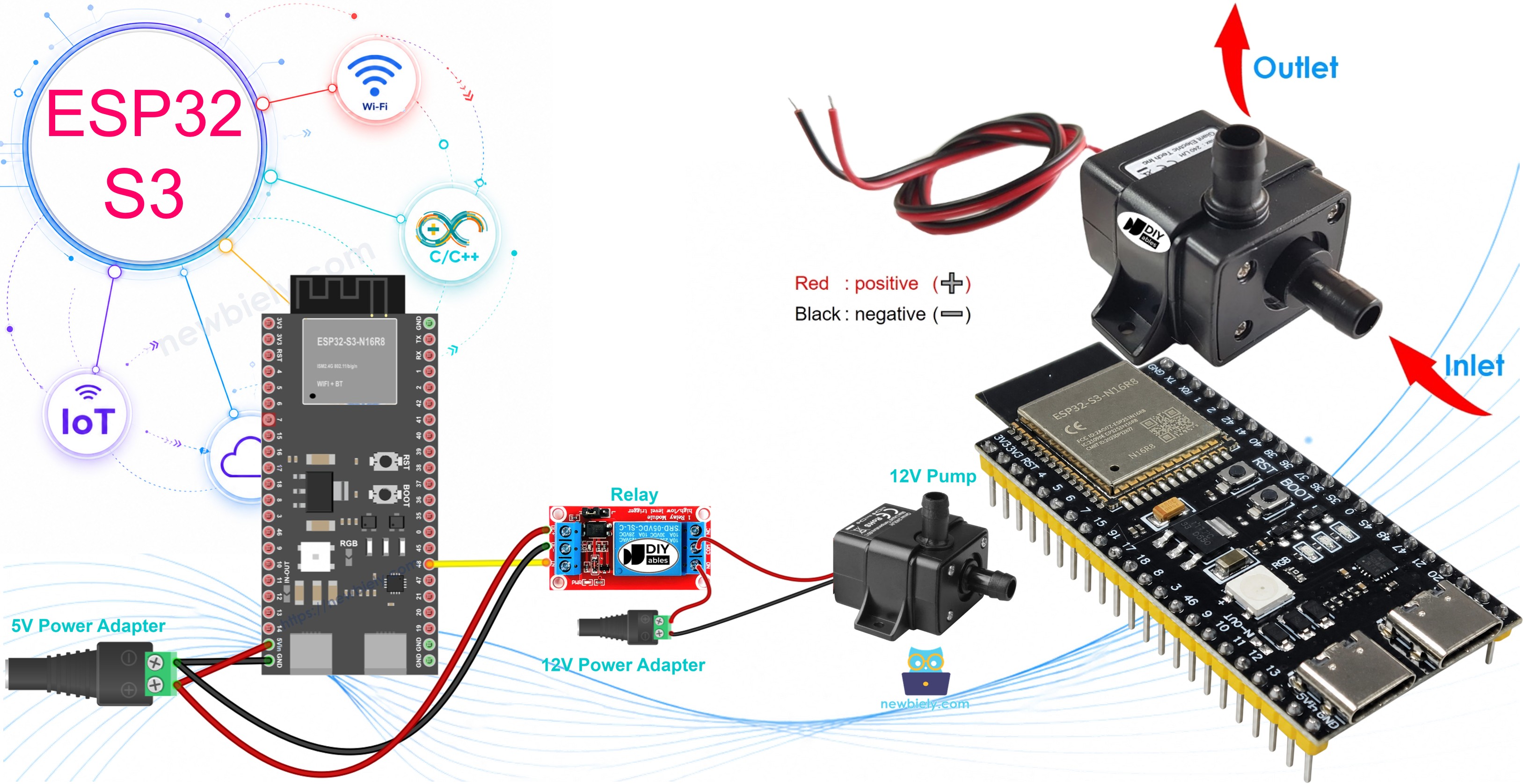
Hardware Preparation
Or you can buy the following kits:
| 1 | × | DIYables ESP32 S3 Starter Kit (ESP32 S3 included) | |
| 1 | × | DIYables Sensor Kit (18 sensors/displays) |
Additionally, some of these links are for products from our own brand, DIYables .
Overview of 12V Pump
A 12V pump is a compact electric water pump powered by 12V DC and widely used in DIY water circulation and automation projects. Its simple two-wire interface makes it straightforward to integrate with microcontrollers like the ESP32 S3 through a relay module.
Key Specifications
The pump operates at 12V DC with a typical power consumption of 3 to 5 watts. Flow rate varies by model but generally falls between 1 and 3 liters per minute, making it suitable for aquariums, irrigation systems, coffee machines, and automated beverage dispensers.
Pump Pinout
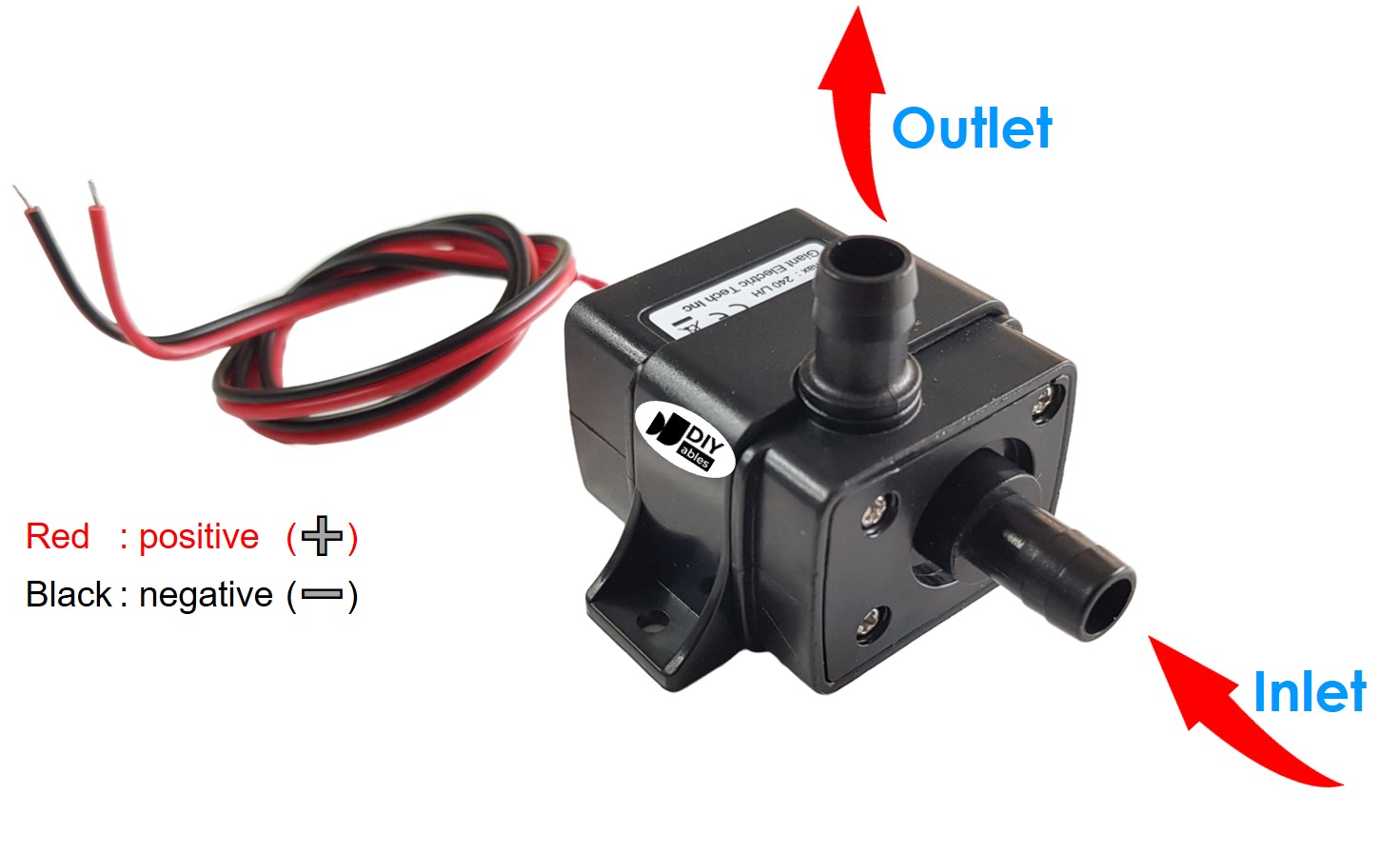
The 12V pump has two wires for connection:
- Negative (-) wire (black): Connect to the negative terminal of the 12V DC power supply
- Positive (+) wire (red): Connect to the positive terminal of the 12V DC power supply
How to Control Pump using ESP32 S3
The ESP32 S3 controls the pump by switching its power circuit through a relay module. Because the pump requires 12V DC and the ESP32 S3 operates at 3.3V logic, it cannot power the pump directly. A relay acts as an electronically controlled switch: when the ESP32 S3 sends a HIGH signal on the control pin, the relay closes and allows 12V current to flow through the pump; when it sends LOW, the relay opens and the pump stops. This arrangement keeps the ESP32 S3 safely isolated from the high-voltage side. For more detail, see our ESP32 S3 - Relay tutorial.
Want to change the flow and not only switch the pump? Then use a MOSFET module. Its terminals, the PC817 inside, and PWM are all covered in our ESP32 S3 - MOSFET Module guide.
Comparing Relay and MOSFET Module for a Pump
| Point | Relay Module | MOSFET Module |
|---|---|---|
| Pump control | start / stop only | start / stop, plus flow rate (PWM) |
| Sound | audible click | silent |
| Response | milliseconds, slow | almost instant |
| Lifespan | metal contacts wear with use | no moving parts inside |
| Works with | AC and DC pumps | DC pumps only |
| Pump supply | any rated voltage | 6V or more (the gate needs it) |
| Isolation | yes (coil vs contacts) | yes (PC817 optocoupler) |
| Best use | AC pumps, simple ON/OFF | 12V DC pumps, adjustable flow, frequent switching |
For the 12V DC pump in this tutorial, both work. Choose the MOSFET module when you want a gentle flow, for example to water small plants. Choose the relay when your pump runs on AC.
Wiring Diagram between ESP32, Relay and Pump
Connect the ESP32 S3, relay module, and 12V pump following the diagram below. Always disconnect power before making or changing any connections, and double-check polarity on the pump and power adapter before applying voltage.
Safety Notes
The relay module separates the low-voltage ESP32 S3 circuit from the 12V pump circuit. Keep the 12V wiring on the relay terminal side well clear of the ESP32 S3 and breadboard area. Verify that the COM and NO terminals are used — never wire to NC for a pump-control setup.
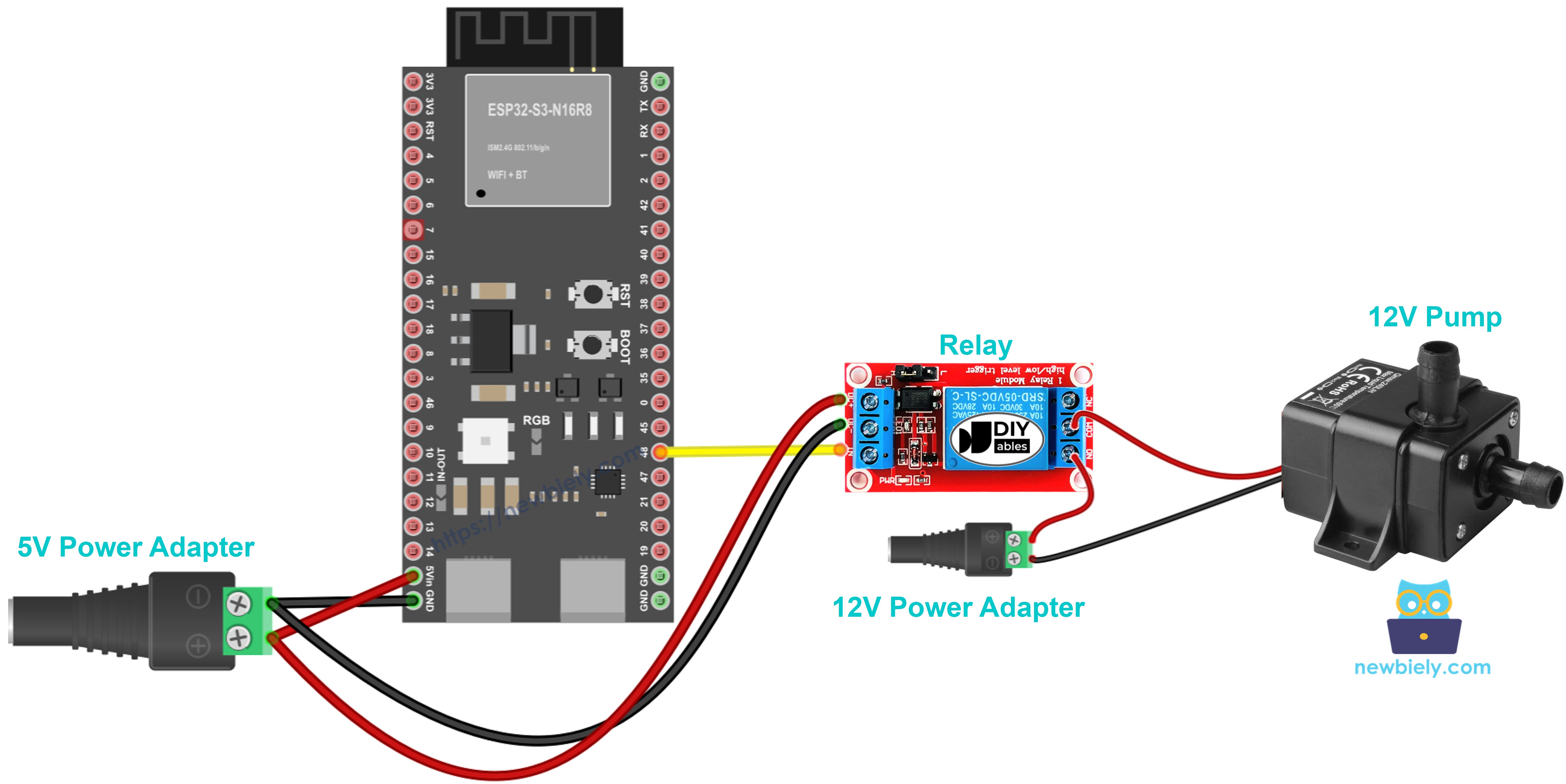
This image is created using Fritzing. Click to enlarge image
| ESP32 S3 Pin | Relay Module Pin |
|---|---|
| D7 | IN |
| GND | GND |
| 3.3V | VCC |
| Relay Module Terminal | Connection |
|---|---|
| COM | 12V Power Adapter (+) Positive |
| NO | Pump (+) Red Wire |
| Ground Connections | Connection |
|---|---|
| 12V Power Adapter (-) | Pump (-) Black Wire |
ESP32 S3 - Pump Code
The following code programs the ESP32 S3 to cycle the pump on and off automatically. It configures pin D7 as the relay control output, then repeatedly turns the pump on for 4 seconds and off for 4 seconds while printing the current state to the Serial Monitor. Each line of the sketch is annotated in the comments for easy reference.
Detailed Instructions
- New to ESP32 S3? Complete our Getting Started with ESP32 S3 guide first.
- Wire the relay, pump, and 12V power adapter following the wiring diagram above.
- Connect the ESP32 S3 to your computer using the USB Type-C cable.
- Open the Arduino IDE on your computer.
- Select ESP32S3 Dev Module (or your specific ESP32-S3 board variant) from the board menu, and choose the correct COM port.
- Copy the code above, paste it into Arduino IDE, and click the Upload button.
- Open the Serial Monitor (baud rate 115200) to watch the pump status messages.
- Observe the pump turning ON and OFF every 4 seconds automatically.
- Pro Tip: Use a clear vinyl tube so you can see water flowing the moment the pump activates, which makes debugging wiring issues much easier.
Line-by-line Code Explanation
The above ESP32 S3 code contains line-by-line explanation. Please read the comments in the code!
Serial Monitor Output
Open the Serial Monitor to see the pump control status in real time. With the 4-second cycle the output will look similar to the following:
Applications and Project Ideas
The ESP32 S3 pump control setup shown here forms the foundation for a wide range of practical automation projects.
- Automated Aquarium: Control water circulation and filtration systems on a timer to keep fish healthy without manual intervention.
- DIY Irrigation System: Water your plants automatically based on a schedule or soil moisture sensor readings.
- Coffee Machine Automation: Build a programmable espresso or drip coffee maker with precise timing control.
- Cocktail Dispenser: Create an automated bartender that dispenses drinks at the push of a button or via a web interface.
- Fountain Controller: Program decorative water fountain patterns and timing sequences for indoor or outdoor displays.
- Hydroponic System: Manage nutrient solution circulation for indoor gardening with scheduled pump cycles.
How to Control Pump Flow with MOSFET Module
This section shows the MOSFET way. With PWM from the ESP32 S3, the pump can run fast, slow, or anywhere in between.
Wiring Diagram between ESP32 S3, MOSFET Module and Pump
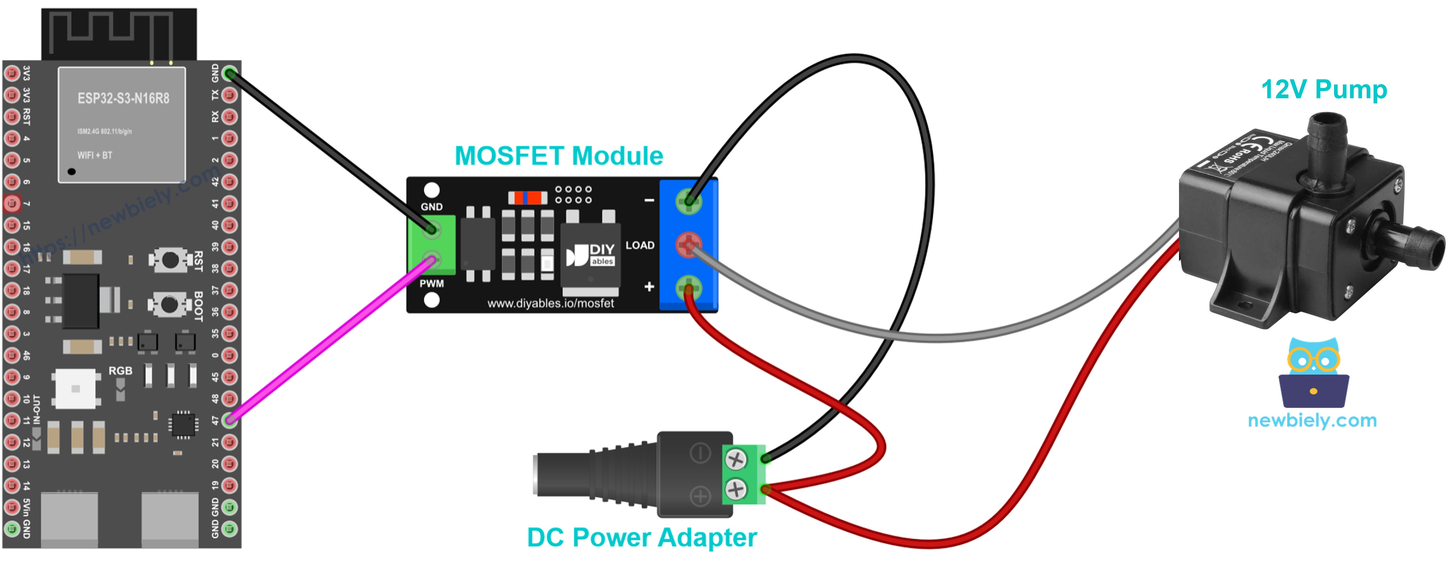
This image is created using Fritzing. Click to enlarge image
| ESP32 S3 / Power | MOSFET Module |
|---|---|
| GPIO47 | PWM |
| GND | GND |
| 12V Power Adapter (+) | + |
| Pump (+) Red Wire | + (same screw as the adapter +) |
| Pump (-) Black Wire | LOAD |
| 12V Power Adapter (-) | − |
The pump motor is a coil, so add a 1N4007 or 1N5819 flyback diode across the pump wires, with the stripe (cathode) on pump +.
ESP32 S3 - Pump Flow Code
The pump first runs at full power for 2 seconds and then stops for 2 seconds. Next, its power climbs from 10% to 100% and falls back to 0%, so the water stream grows stronger and then weaker.
Detailed Instructions
- Use the same board setup as in the relay Quick Steps above.
- Wire the MOSFET module, pump, and 12V adapter as shown. Put the pump in water first.
- Upload the code, then power the 12V adapter.
- Open the Serial Monitor at 9600 baud.
- Watch the water flow change along with the power value.
Pro Tip: The MOSFET module only switches DC, and the pump supply should be at least about 6V. If your pump is an AC model, use the relay circuit above.
Video Tutorial
Watch the step-by-step video walkthrough for this ESP32 S3 project below.
Challenge Yourself
These challenges will help you build on the basic pump control sketch and develop more advanced automation skills.
- Beginner: Modify the code to change the ON/OFF timing intervals to 10 seconds each and observe the difference.
- Beginner: Add an LED indicator that lights up whenever the pump is running so you have a visual status signal.
- Intermediate: Add a push button to manually start and stop the pump independently of the automatic timer.
- Intermediate: Connect a soil moisture sensor and activate the pump only when the soil reading drops below a set threshold.
- Advanced: Create a web interface using the ESP32 S3's built-in WiFi to control the pump remotely from a phone or browser.
- Advanced: Build a complete multi-pump irrigation system where each pump runs on its own independent schedule stored in EEPROM.