
ESP32 S3 - Piezo Buzzer
Learning to generate sound with a piezo buzzer on the ESP32 S3 opens the door to audio feedback, alarms, and even simple melodies in your embedded projects. This tutorial walks you through everything — how the buzzer works, how to wire it to your ESP32 S3, and how to write code that produces both a beep and a full musical tune.
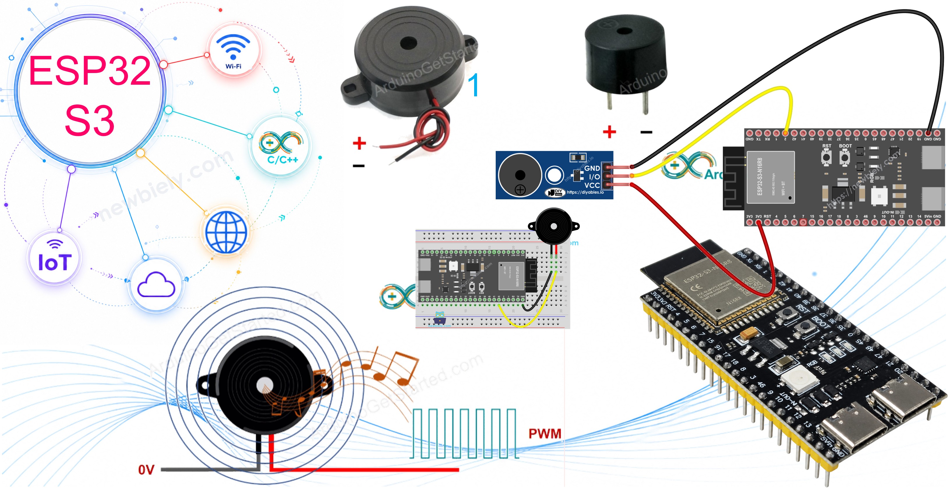
What you'll build:
- A circuit connecting a piezo buzzer (or buzzer module) to the ESP32 S3
- A sketch that plays a melody using PWM tone generation
- A modified version that plays Jingle Bells with custom note arrays
- A foundation for real-world audio applications such as alarms, notifications, and music boxes
Hardware Preparation
Or you can buy the following kits:
| 1 | × | DIYables ESP32 S3 Starter Kit (ESP32 S3 included) | |
| 1 | × | DIYables Sensor Kit (18 sensors/displays) |
Additionally, some of these links are for products from our own brand, DIYables .
Overview of Piezo Buzzer
The piezo buzzer is an electronic component that converts electrical signals into sound, making it ideal for beeps, alerts, and even musical melodies. A popular choice for ESP32 S3 projects is the 3V-24V active buzzer, which is versatile enough to work as a low-voltage buzzer connected directly to a GPIO pin or as a high-voltage alarm buzzer switched through a relay.
Key Specifications
When connected directly to an ESP32 S3 GPIO pin at 3.3V, the buzzer produces a clear standard-volume tone — perfect for keypad feedback or status indicators. When switched through a relay and powered from a 12V or higher source, it emits a loud alarm-level sound suited for warning systems. Buzzer modules include an onboard transistor driver and accept a PWM signal from the ESP32 S3, making them easier to control without worrying about current limits on the GPIO pin.
Piezo Buzzer Pinout
A bare piezo buzzer typically includes two pins:
- Positive (+) pin: Receives the control signal from the ESP32 S3 GPIO (directly or via relay)
- Negative (-) pin: Connects to GND (0V)
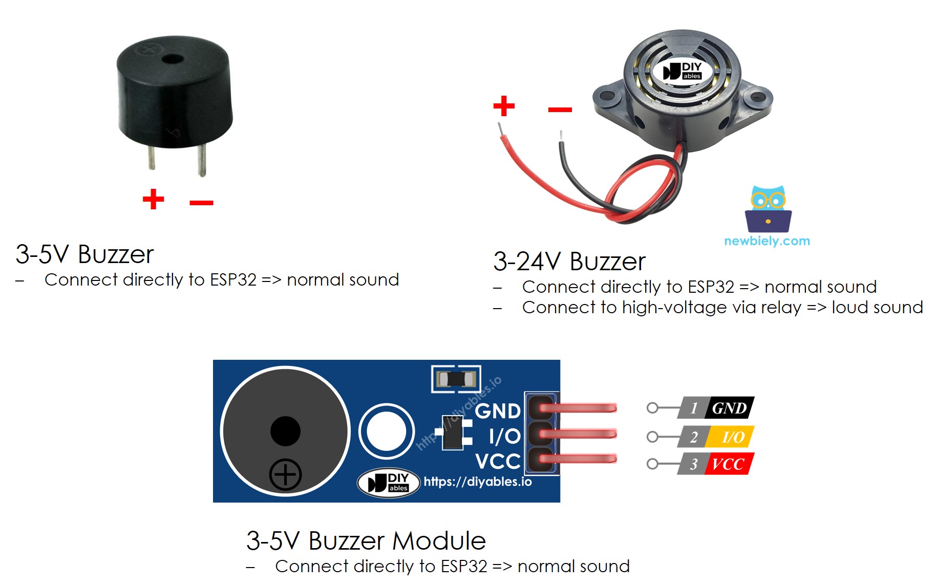
A piezo buzzer module typically includes three pins:
- GND pin: Connects to GND (0V)
- VCC pin: Connects to VCC (5V or 3.3V)
- I/O pin: Receives the PWM control signal from an ESP32 S3 GPIO pin
How Piezo Buzzer Works
Wiring Diagram between Piezo Buzzer and ESP32 S3
The following diagrams show how to connect either a bare piezo buzzer or a buzzer module to your ESP32 S3. Both configurations use a single GPIO pin for signal output, making them straightforward to set up on a breadboard.
Safety Notes
The GPIO pins on the ESP32 S3 operate at 3.3V logic. A bare piezo buzzer connected directly to a GPIO pin draws minimal current and is safe within this limit, but never connect a high-voltage buzzer directly without a relay or driver circuit. Use the buzzer module if you are unsure, as its onboard driver handles the current safely.
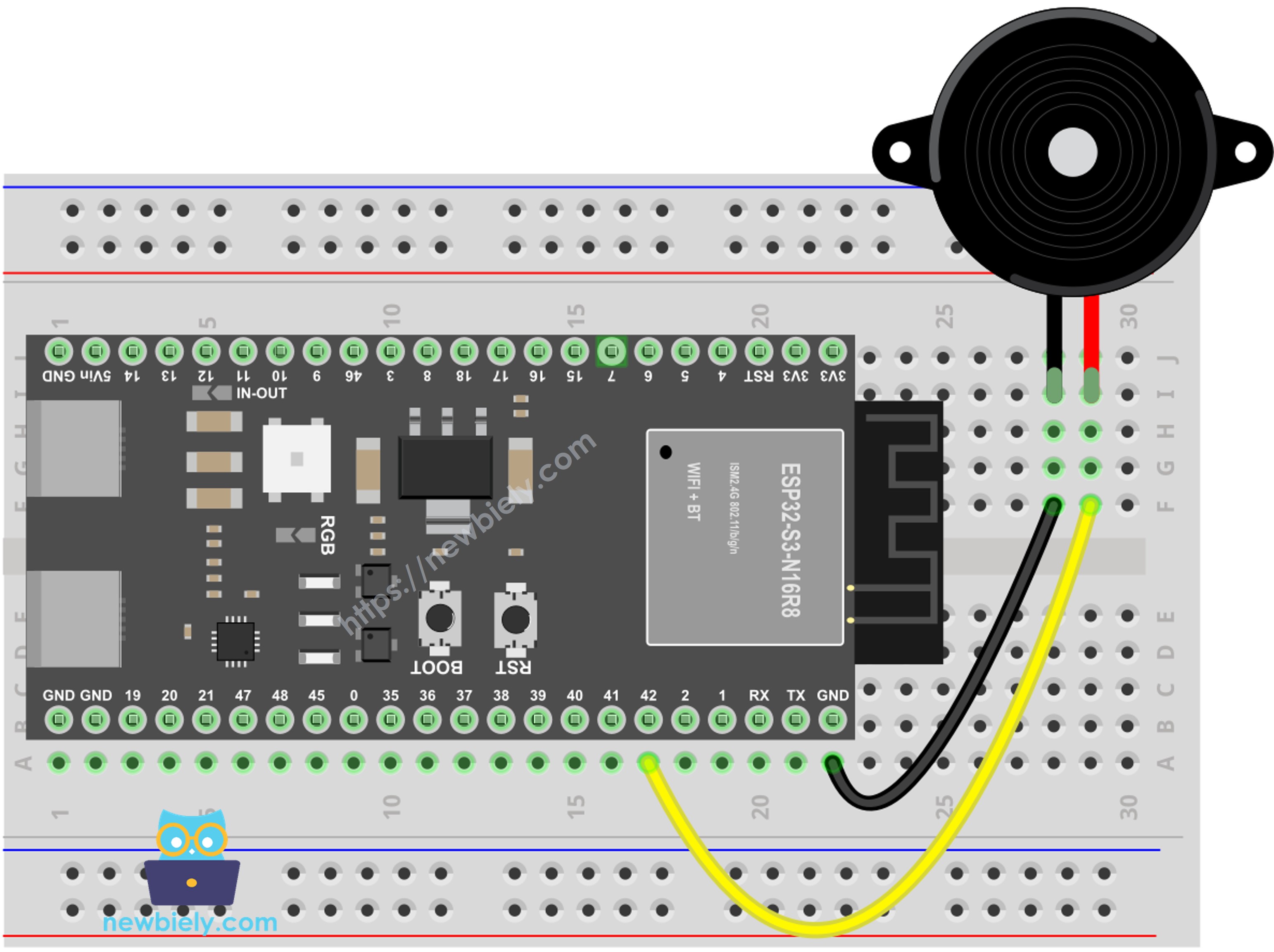
- The wiring diagram between piezo buzzer and ESP32 S3
This image is created using Fritzing. Click to enlarge image
| Buzzer Pin | ESP32 S3 Pin |
|---|---|
| Positive (+) | GPIO42 |
| Negative (-) | GND |
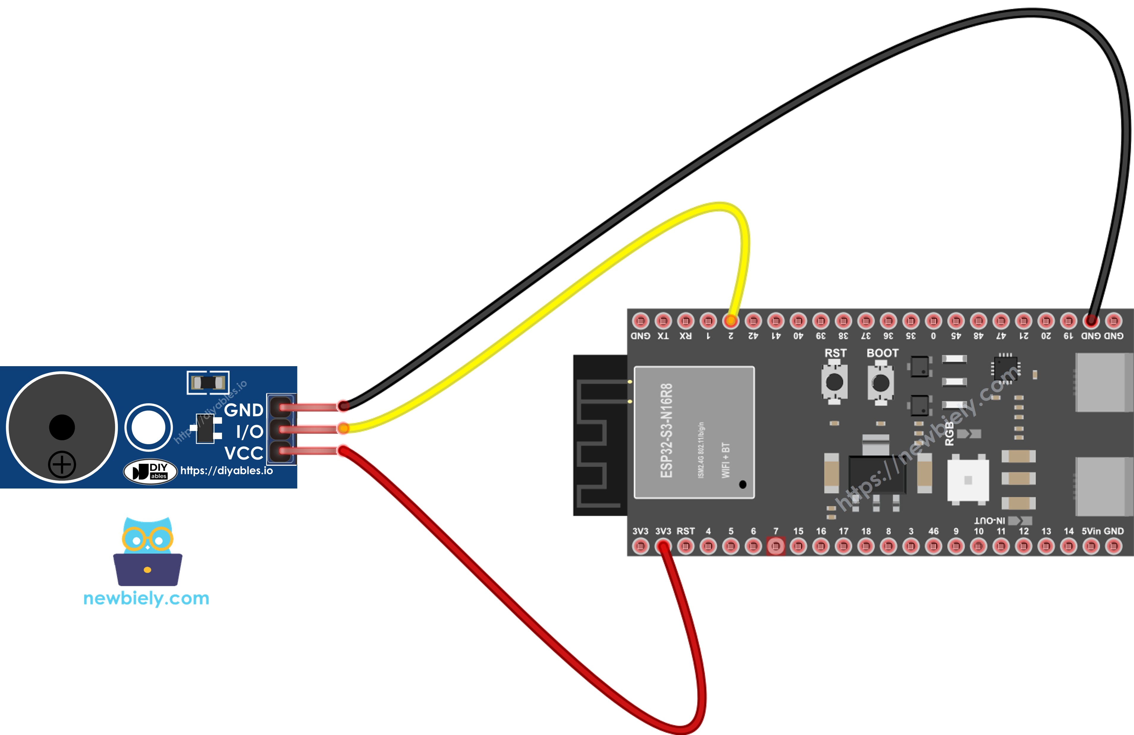
- The wiring diagram between piezo buzzer module and ESP32 S3
This image is created using Fritzing. Click to enlarge image
| Module Pin | ESP32 S3 Pin |
|---|---|
| GND | GND |
| VCC | 3.3V |
| I/O | GPIO42 |
ESP32 S3 Code
The following sketch uses Arduino's built-in tone() function to drive the piezo buzzer with PWM signals, producing musical notes at defined frequencies and durations. It relies on a companion pitches.h header file that maps note names (like NOTE_C4, NOTE_G3) to their corresponding frequencies in Hz, which keeps the melody array readable and easy to modify.
Detailed Instructions
- New to ESP32 S3? Complete our Getting Started with ESP32 S3 guide first.
- Wire the components: Follow the wiring diagram shown above.
- Connect your board: Plug the ESP32 S3 into your computer via USB cable.
- Open Arduino IDE: Launch the software on your computer.
- Select your board: Choose ESP32 S3 and the correct COM port.
- Upload the main sketch: Copy the code below and paste it into Arduino IDE.
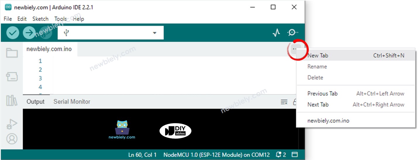
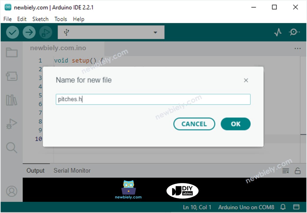
- Create the pitches.h file in Arduino IDE by:
- Either click on the button just below the serial monitor icon and choose New Tab, or use Ctrl+Shift+N keys.
- Give the file the name pitches.h and click the OK button.
- Copy the code below and paste it into the newly created pitches.h file.
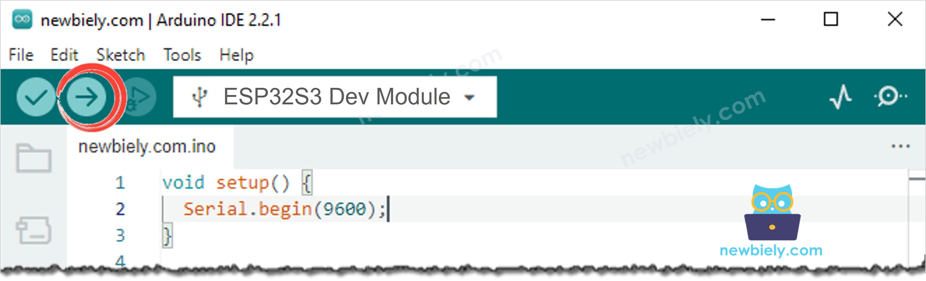
- Compile and upload: Click the Upload button in Arduino IDE.
- Listen to the melody: The ESP32 S3 will play the melody through the buzzer.
- Pro Tip: If you hear no sound, double-check the buzzer polarity — the positive (+) pin must connect to GPIO42, and the negative (−) pin to GND.
Serial Monitor Output
Modifying ESP32 S3 Code
Let's modify the ESP32 S3 code to play the Jingle Bells song. Only the values of two arrays need to change — int melody[] holds the sequence of note constants, and int noteDurations[] specifies how long each note lasts. Everything else in the sketch remains identical, which makes it easy to swap in any melody you like.
Application/Project Ideas
The piezo buzzer is a surprisingly versatile output device that adds an audio dimension to almost any ESP32 S3 project.
- Alarm System: Sound a buzzer when a motion sensor or door sensor is triggered, giving your ESP32 S3 security project an audible alert.
- Keypad Feedback: Play a short beep each time a key is pressed on a matrix keypad to confirm user input.
- Timer Alert: Signal the end of a countdown timer with a multi-tone pattern — useful in kitchen timers or Pomodoro productivity tools.
- Music Box: Store multiple melodies in flash memory and select them with a button, turning your ESP32 S3 into a simple music player.
- Distance Warning: Pair the buzzer with an ultrasonic sensor and increase the beep frequency as an object gets closer, similar to a parking sensor.
- Low-Battery Indicator: Monitor a battery voltage divider and sound a warning tone when the voltage drops below a safe threshold.
Video Section
Watch the step-by-step video walkthrough for this ESP32 S3 project below.
Challenge Yourself
These exercises will deepen your understanding of buzzer control on the ESP32 S3, progressing from basic tone generation to more creative audio applications.
- Beginner: Modify the melody array to play "Happy Birthday" using note constants from pitches.h.
- Beginner: Add a button so the melody only plays while the button is held down.
- Intermediate: Create a doorbell effect — play a two-note chime each time a push button is pressed, with a cooldown period between rings.
- Intermediate: Use the noTone() function to build a Morse code transmitter that beeps out a short text message.
- Advanced: Implement a frequency sweep from 200 Hz to 4000 Hz to find the resonant frequency of your buzzer and produce the loudest possible output.