
ESP32 S3 - SW-420 Vibration Sensor
An ESP32 S3 paired with a SW-420 vibration sensor can catch a knock, a shake, or a sudden jolt the instant it happens, which makes it a great starting point for alarms, shipping monitors, or simple shake-activated gadgets. This tutorial walks through wiring the module and writing the firmware needed to react to that vibration in real time.
What you'll build:
- An overview of how the SW-420 module senses shock and vibration
- A wired connection between the SW-420 module and the ESP32 S3
- Firmware that watches the sensor's digital pin and reacts to changes
- Serial Monitor output confirming vibration events as they start and end
Once the basic sketch is running, you can extend it to sound a buzzer, send a WiFi alert, or drive a relay whenever a shock is detected.
Hardware Preparation
Or you can buy the following kits:
| 1 | × | DIYables ESP32 S3 Starter Kit (ESP32 S3 included) | |
| 1 | × | DIYables Sensor Kit (18 sensors/displays) |
Additionally, some of these links are for products from our own brand, DIYables .
Overview of SW-420 Vibration Sensor
The SW-420 Vibration Sensor Module detects shock and vibration using a small spring-based switch mounted next to a metal contact. Any knock or shake disturbs the spring, and an onboard LM393 comparator turns that disturbance into a clean digital signal the ESP32 S3 can read directly - there's no analog pin or extra math involved.
Key Specifications
- Operating voltage: 3.3V to 5V DC
- Digital-only output (no analog pin on this module)
- Sensitivity adjustable through an onboard potentiometer/trimmer
- Comparator: onboard LM393
- Onboard power LED plus a trigger LED for the digital output
The SW-420 Vibration Sensor Pinout
Three pins on the SW-420 module connect straight to the ESP32 S3, no extra components needed.
- VCC pin: Connect to power supply (3.3V to 5V)
- GND pin: Connect to ground (0V)
- DO pin: Digital output pin - stays LOW while idle and switches HIGH the moment vibration or shock is detected - connect to ESP32 S3 digital input pin
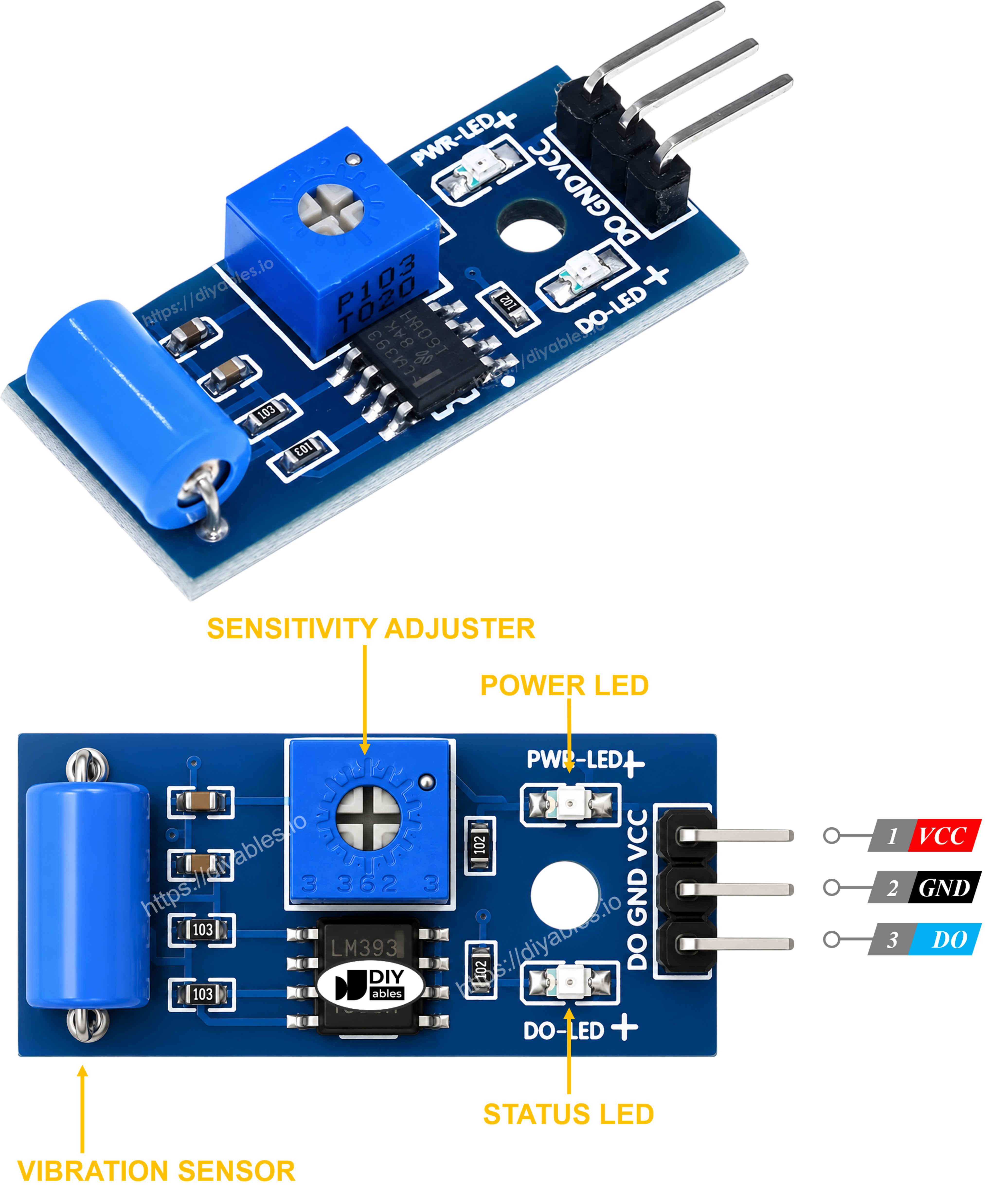
Additional features:
- Power LED indicator confirms the module is receiving voltage
- Trigger LED lights up whenever the DO pin goes HIGH, handy for testing without a Serial Monitor
- Onboard potentiometer tunes how much shaking is needed before DO trips HIGH
How It Works
The spring switch inside the SW-420 either rests undisturbed or gets knocked into brief contact, and the comparator turns that into a signal your sketch can poll.
Digital output behavior:
- At rest, with no vibration: the spring switch stays open → output pin reads LOW
- The instant vibration or shock disturbs the spring: the switch momentarily closes → output pin reads HIGH
Wiring Diagram
Wire the SW-420 module's three pins to the ESP32 S3 as shown below, keeping the connections short and secure on the breadboard.
Safety Notes
Match the VCC wire to a 3.3V or 5V pin on your ESP32 S3, never anything higher, and make sure GND is solidly connected since a floating ground is a common cause of a DO pin that never settles. If the module still triggers randomly after wiring is confirmed, turn the onboard potentiometer to lower its sensitivity before suspecting the code.
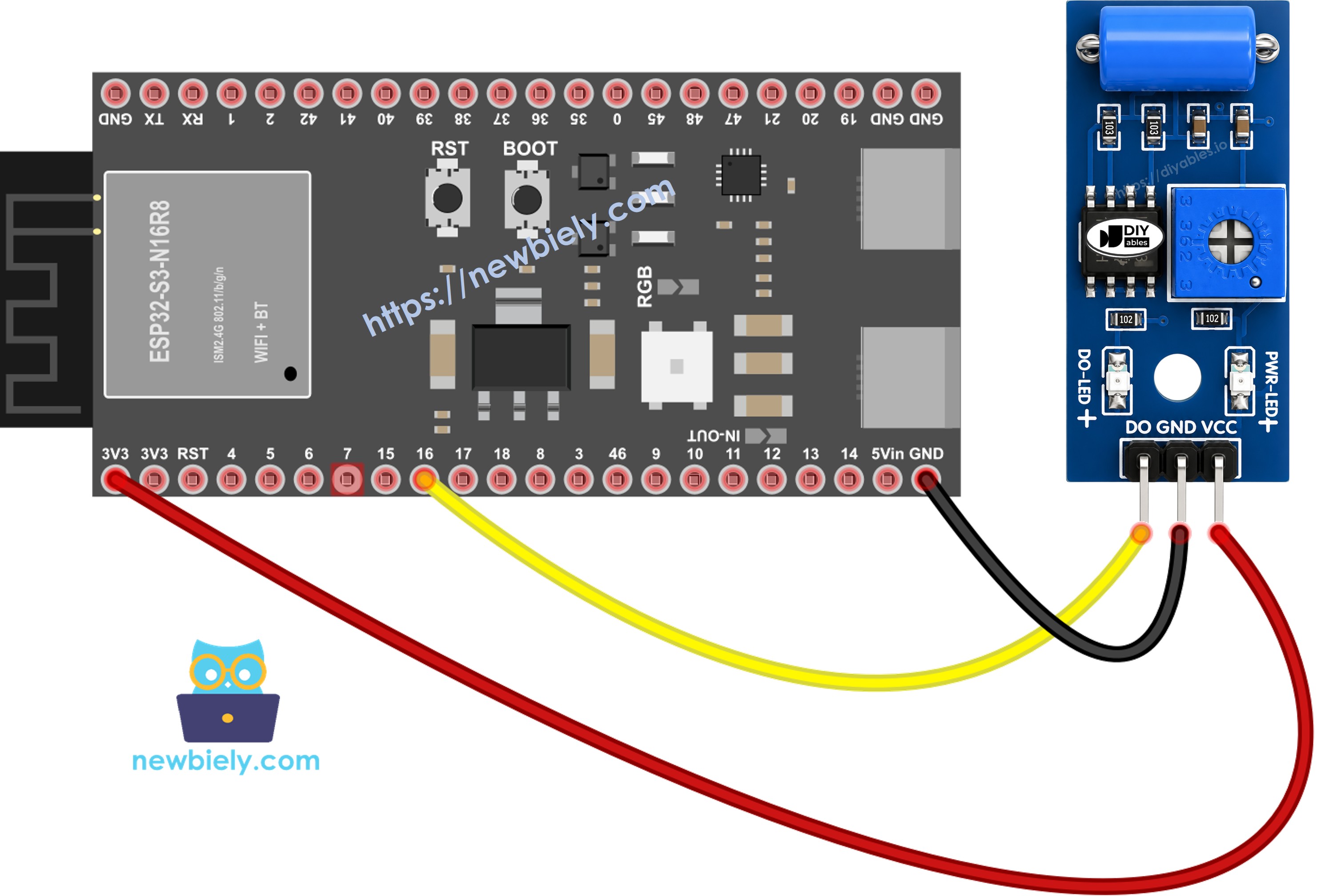
This image is created using Fritzing. Click to enlarge image
| SW-420 Vibration Sensor Pin | ESP32 S3 Pin |
|---|---|
| VCC | 3.3V or 5V |
| GND | GND |
| DO | D16 (GPIO16) |
How To Program For SW-420 Vibration Sensor
The firmware only needs to set up one digital input pin and then watch it change state inside the loop. Below, pin D16 is configured as an input and polled continuously, and the sketch prints a message to the Serial Monitor the moment the reading flips from idle to triggered, and again once it settles back down.
Step 1 - Configure the input pin:
Step 2 - Poll the current reading:
ESP32 S3 Code - Detecting vibration
Detailed Instructions
- New to ESP32 S3? Complete our Getting Started with ESP32 S3 guide first.
- Check the wiring: Match every wire to the diagram above before powering the board
- Copy the code: Copy the sketch above into a new Arduino IDE window
- Select your board: Choose ESP32 S3 from the boards menu
- Upload the sketch: Click Upload to flash the code onto your ESP32 S3
- Open Serial Monitor: Set the baud rate to 115200
- Give it a tap: Gently knock or shake the SW-420 module
- Watch the readings: Confirm the Serial Monitor logs a detected/stopped pair for each tap
- Pro Tip: If every tiny knock triggers it, turn the onboard potentiometer clockwise or counter-clockwise a little at a time until the sensitivity feels right for your project
From here, swap the Serial.println() calls for anything you need - light an LED, latch a relay, or fire off a notification - the moment vibration is detected. The project ideas and challenges below offer a few directions to take it.
Application and Project Ideas
A digital vibration switch this simple fits into far more than lab demos - here are a few ways to put it to work with an ESP32 S3.
- Shock Alarm: Trigger a buzzer or siren the instant an unexpected knock or impact is detected
- Package Shock Logger: Log timestamps of every jolt a parcel experiences in transit
- Washing Machine Imbalance Monitor: Flag excessive shaking during a spin cycle before it becomes a problem
- Tutorial Tool Safety Monitor: Detect abnormal vibration on a running power tool and cut power automatically
- Mini Seismograph Demo: Chart vibration events over time for a simple earthquake-detector-style classroom project
Video Tutorial
Watch the step-by-step video walkthrough for this ESP32 S3 project below.
Challenge Yourself
Try these challenges to build on the basic vibration sketch and push your ESP32 S3 project further.
- Beginner: Light an LED the moment vibration is detected and turn it off once things settle
- Beginner: Show the vibration state on an LCD instead of only the Serial Monitor
- Intermediate: Keep a running count of vibration events and print a total every minute
- Intermediate: Wire the sensor to a relay so a shock automatically cuts power to another device
- Advanced: Combine readings from several SW-420 modules placed around an object to map where vibration is strongest
Troubleshooting
If your ESP32 S3 and SW-420 vibration sensor aren't behaving as expected, work through these checks.
Common issues and fixes:
- Adjust the potentiometer: Too sensitive and it fires on every footstep; too dull and it misses real taps - turn the onboard trimmer gradually and retest after each turn
- Isolate from ambient vibration: Mount the module away from motors, fans, or a shaky table so background rumble doesn't masquerade as a real event
- Check wiring: Reconfirm VCC, GND, and DO all match the wiring diagram - a loose DO wire looks identical to "no vibration" on the Serial Monitor
- Verify power supply: An unstable or noisy 3.3V/5V source can make the comparator output chatter on its own
- Watch the trigger LED: The onboard LED should flash in step with each knock - if it doesn't, the fault is on the sensor side, not in your code